Recommended Sites


Polar Lights Models: Klingon K’t’inga buildup process Pt.2
Continuing our series of guest blogs covering our brand-new STAR TREK: The Motion Picture 1:350 Klingon K’t’inga model kit…
The Ktinga Building, Part One
James Small, www.smallartworks.ca
Oh, OK, I won’t bother with the double entendres and food jokes with this one. Just the straight up dope this time, albeit not with a lot of pictures. Most of my time was spent just looking through the parts, test fitting and comparing them to the CG model (used for the tooling) and gaining an understanding of what goes where and when certain parts should be assembled and which ones should be left off until lighting and painting can be done. That’s the way it goes when you’re building a kit (actually three of them in this case) for the first time without the instructions that will be included in the final kit! I’m also doing what I can to document it for both this blog and for possible ways to make minor improvements in the kit as we go along so such changes can be incorporated into the kit as you people will be buying it. The test shots have been done, but small improvements will still be made, which is why they are called TEST shots. Also, I wanted to actually get PAST the points covered in this blog to make sure I covered it all needed before the next. Lotsa back-and-forth with this one.
First, I will let you know that I will be describing this build with the lighting kit being installed, as this is the most comprehensive way to do it. If you will NOT be installing the lighting (why would you NOT want to light it up???) then you can take obvious shortcuts, but I will not deal with those shortcuts here.
I wanted to assemble as much of the sub assemblies as I could before the lighting or painting needed to be applied. That part turned out to be a bit tricky as this is one of those models you need to do a little bit of each as you go along. That means there will be assemblies you will build, then you will install SOME lighting, then you will build some more, do a little painting, then put in more lighting, then more building, and back and forth and so on until it is finished.
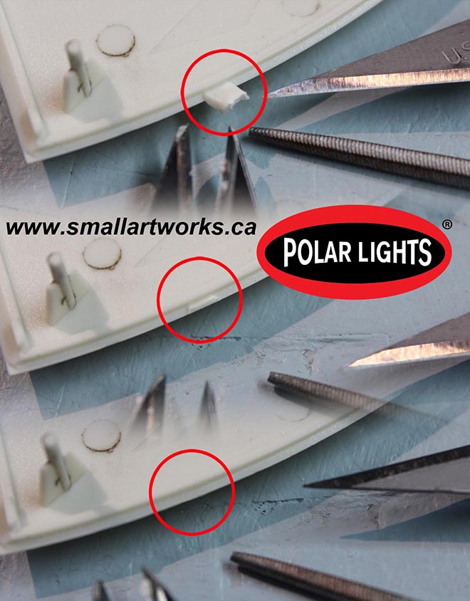
The next thing I want to talk about is how to properly remove the parts from the runners. There are a lot of delicate corners and edges on this one, but if you are careful removing the runner gates, no putty will be needed to smooth things out or hide joints. The pic FIG 1 shows the procedure. First, cut the part from the runner while still leaving a good chunk of the gate attached to the part. Then, using your nippers or a sharp blade, slowly whittle off the remaining nub. Finish the surface off using a needle file. The better you do this on EVERY PART of the model, the better the parts will fit.
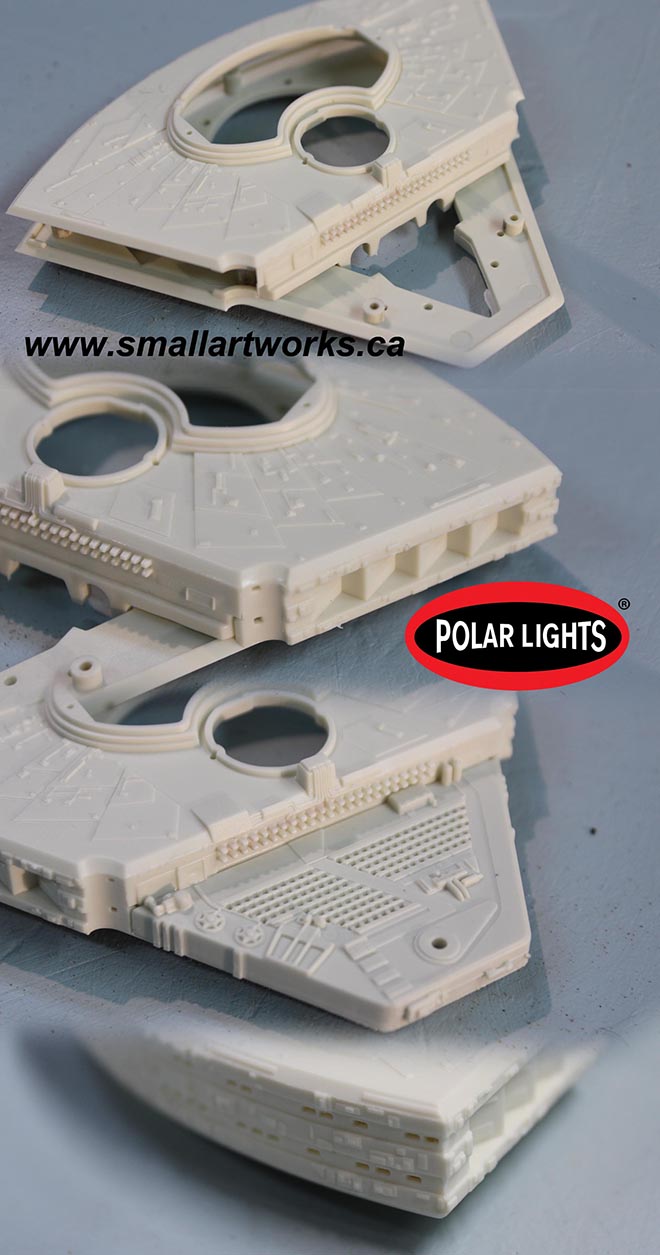
The first parts I assembled were the “Cobra Heads” of all three models. When the above parts preparation procedure is followed and you take your sweet time assembling, the parts fit together absolutely perfectly with no puttying needed and almost no cleanup except for a slight scraping of the edges with a sharp knife after the glue has set. The procedure used to properly glue these parts was covered in an article I did years ago for Round 2’s now defunct “Workbench” page, but can be viewed here on the Small Art Works hosted CNSM page for those of you who would like a refresher.
http://www.smallartworks.ca/CNSM/VS%20build/Pretty%20In%20Mauve.html
Note in FIG 2 that no putty was needed to successfully assemble the parts which are well engineered. I’ll let you in on a little secret here. Although some modelers demand such amenities (which is why Round 2 provides them), I deliberately did NOT use the clear window parts supplied with the kit that would normally be installed behind the outer hull window panels. I find that too difficult to work with (though some modelers have no problems with it). I instead will leave the windows unglazed, then after painting I’ll fill the window holes with Testors “Clear Parts Cement and Window Maker”. Microscale makes a similar product called “Micro Crystal Clear”. In a p[inch white glue would even work but white glue is not as transparent. Then, when the model is finished, a clear dullcoat spray will fog the windows enough to provide properly diffused lighting from the LED’s inside.
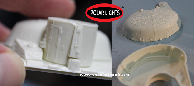
Because it called out to me, I quickly assembled the bridge cylinder and the elliptical section that sits on top of the cobra head because those were so easy to do. The elliptical section glues together so well that the gap is unnoticeable as it falls on a natural panel line. Then I glued the cylinder to the cobra head section and noticed a GAP! OH NO! Naw, false alarm. The gaps that you see in the pictures are actually supposed to be there. It’s likely a result of the original VFX miniature being made that way, because the bridge section was made removable for maintenance and so, yes, those gaps are authentic! So before everyone complains, that is NOT an error of the kit! See FIG 3. Very little clean up was needed between the two cylinder halves.
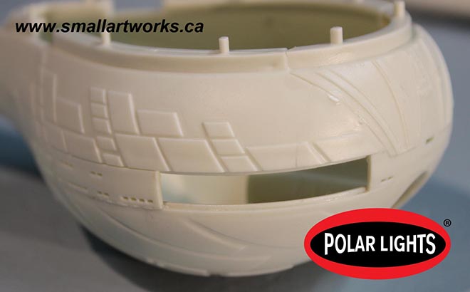
The next thing I assembled was the lower part of the head which I call the “bulb”… because… duh… that’s what it looks like. The best way to go about this (hey, I had three tries, eh?) is to cement the forward part of the top half of the bulb together with the two sides of it so that all three parts of the top half of the bulb are properly aligned. Do this while continually testing (but not gluing it) to the cobra head section that will eventually be permanently mated with it. Then, when the glue has set, cement the top to the bottom half and then glue the window sections in place as shown in FIG 4. The torpedo tube was also glued in at this time as well. Any slight overlap of the window section relative to the bulb section can be easily trimmed down or disguised by the fact that the entire window section will be painted black, so the parts seam line will be naturally disguised by that very obvious colour difference. This deficiency is being worked on by the factory to improve the fit. Also, a decal for the darks tripes that go over the windows will be provided. The bulb is NOT glued to the cobra head yet. That will be done after the model is painted and the lighting is installed.
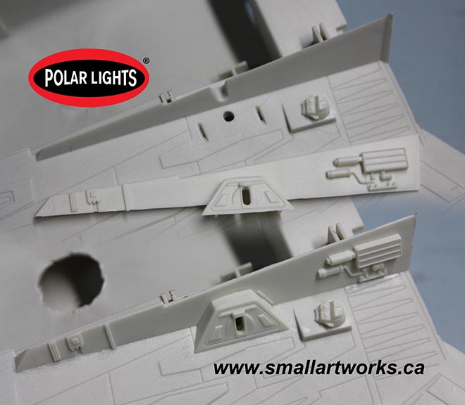
Next I glued on some rather insignificant detail parts (FIGS 5 & 6) because there were bits that would need to blend into the finished model which did not need any special treatment and could be added without being detrimental to the lighting system that would later be installed or impede paint work.
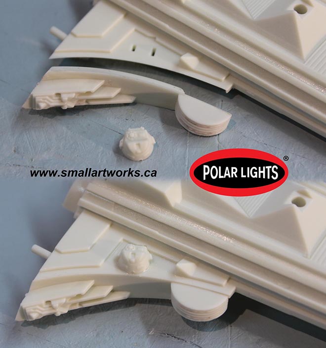
The sharp eyed observer will notice the direct tie in to Star Wars on this model. Yes, the foot pad from the R2 D2 MPC model kit was actually used on the original filming miniature exactly as you see, tying Star Trek and Star wars together the way only ingenious model makers can! In this case, R2’s foot was used as the vehicle from which the Klingon insignia spotlight would shine. See FIG 6.
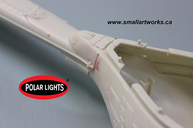
I did find just one spot that needed some putty between the joints, but it’s a very easy fix. See FIG 7
Quite a bit more has been done to the model since these photos were taken which will be covered in the next installment.
I’m loving this… and I never recognized that part as Artoo’s foot!
The one thing I was HAPPY to see on the neck, but not as happy to see on the underside cobra-head and upper rear secondary hull, was the disruptor turrets. The ones on either side of the base of the neck are separate parts, and could (in theory) be replaced with super-detailed parts with rotating turret elements, but the others I’ve seen appear to be “permanently molded in” and will be more challenging to remove and replace with “poseable” or even “moveable” turrets.
The Turrets are all separate.
Ah… good to hear. “Appears to be” was phrasing chosen intentionally to let someone correct things if what “appears” was not actually so. 😀
thanks allot just as i get done drooling over the last update you put this one out drooling again thanks cant wait to get my drool soaked hand on it
Nice work as always Jim. This kit is the perfect match for the same scale TOS & Refit Enterprise kits. Good job Jamie and company.
Beautiful kit and excellent build out!! Can we hope/wish this kit eventually translates to a 1/1000 version of the K’tinga??