Recommended Sites


Archive for June, 2019
Space: 1999 Models: New 1/72 scale Eagle kit Pt. 6
If you think you are experiencing deja vu, it isn’t just you… This post was published in error earlier. Here it is again following the correct order. Continuing our guest series reviewing the new 1/72 Eagle test shots. Enjoy!
Getting Ready for Paint!
By E. James Small
OK folks, here we are on the home stretch before we break out the spray cans and air brushes!
If there is one part of this model that is the most confusing, it’s the shoulder pods. Yes, they are simple to build, but really easy to screw up parts orientation, so if there’s one place where you REALLY have to pay close attention to the instruction diagrams, it’s here. These are the assemblies that you triple check before applying glue. I’ve even seen some of those lower cost “pro” builders get that stuff wrong on the larger 22” model! Meh, you get what you pay for I guess.
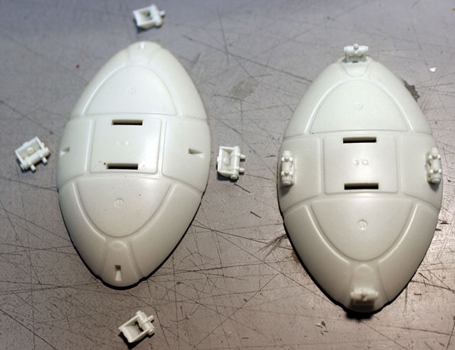
First you need to understand how the detailing on the pods work on the Eagle. Note that the pods are mirrored front to back and side to side. In other words, the detailing on the pods left to right are mirrored from each other and the details between the front and rear are also mirrored… except for ONE detail…
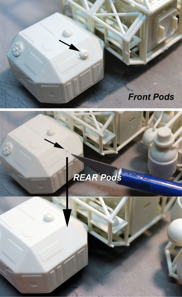
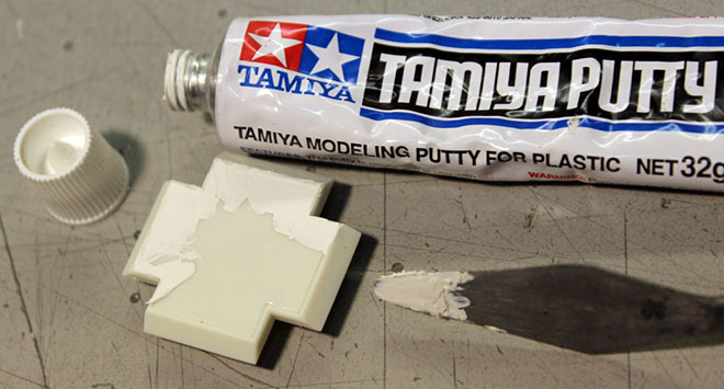
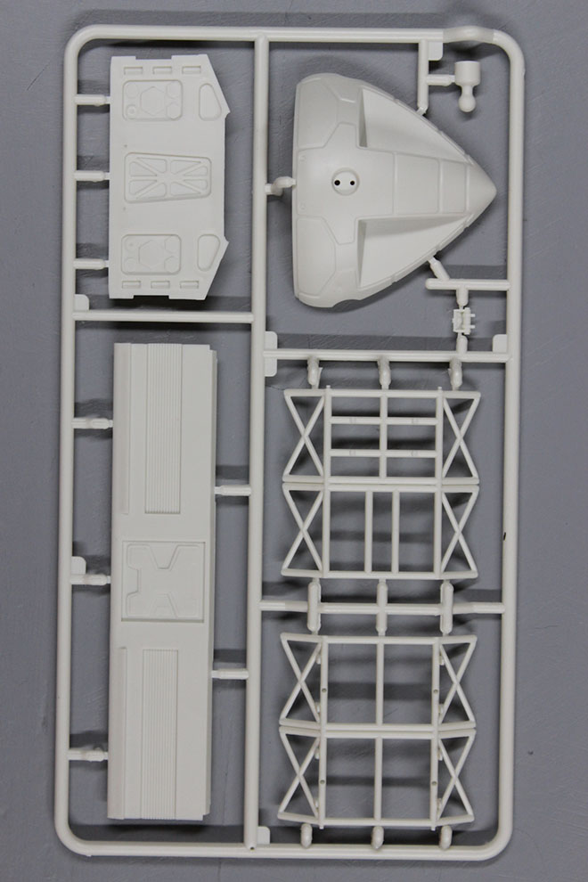
Note that the little dome shown by the arrow on the front pods are left off on the rear pods, so you’ll need to carve or sand off the little locator tab on the rear surfaces as shown. Of course, if you WANT to, you can also put domes on the rear pods too. It’s just that they were left off on the original for some reason. The footpads are two pieces and simple enough but there is a seam/joint running around the bottom that needs to be filled in and then, when putty is fully dry, sanded down.
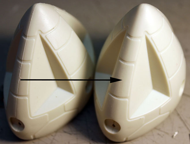
The nosecone assembly is best handled like this:Put the two main halves together, dry. Then using water thin liquid cement, touch a few drops along the joint, allowing the cement to “wick in” and get carried along the joint with capillary action. Then, after the solvent has worked at melting the plastic for a few seconds, firmly press the two halves together, making he plastic/solvent squish out the sides. DO NOT WIPE IT OFF. Allow it to dry like that overnight. Then, when dry, you can sand down the joint nice and smooth and no puttying is needed. Most joints on the kit can be handled this way. The footpad bottoms, as above, seem to be the only exception.
Now glue the nosecone clamps to the back of the nosecone section. Before the glue sets, offer the assembly to the front cage section to make sure the pins locate properly to the holes in the frame.
Now glue the frames to the spine (watch orientation!! Doors on cage boxes point towards each other!) and you should have all the subassemblies as shown in this final picture below. Some parts, such as the little sensor dishes for the nosecone and the black ribbed bits for the top of the Passenger Pod doorframe are left attached to the runners for easier handling when painting. Do what is easiest for you. I left out the assembly procedure for some of the simpler parts like the engine bells as that should be a no brainer. Clean up any unsightly seams etc. following standard modelbuilding procedures. At this stage you are ready to begin painting. That will be covered in a later post. Stick around!
Space: 1999 Models: New 1/72 scale Eagle kit Pt. 5
Welcome back! Your eyes do not deceive you! This continues our guest series reviewing the new 1/72 Eagle test shots. Enjoy!
Engines of Construction.
By E. James Small
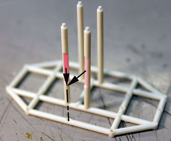
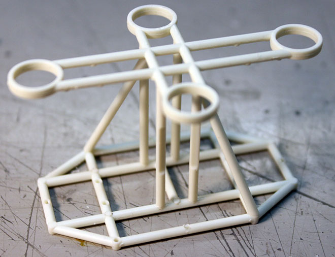
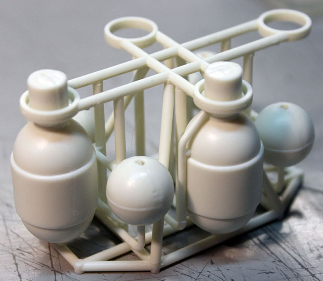
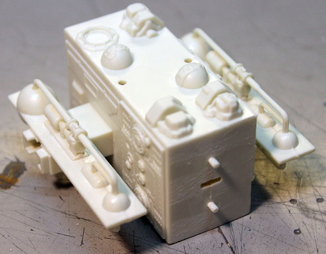
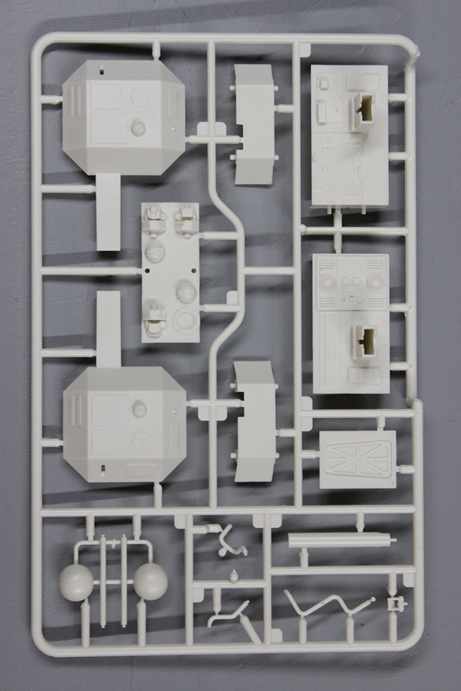
For many people, doing this engine assembly might be the trickiest part with all the piping and so forth, but if you follow this procedure, you will find it actually pretty easy. First grab the octagonal engine mounting main frame and the four supports with flats as shown. Glue them in place, making sure the flats (tinted red in this photo) point toward the centerline of where the top and bottom engines will be mounted. See arrows.
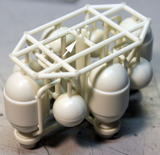
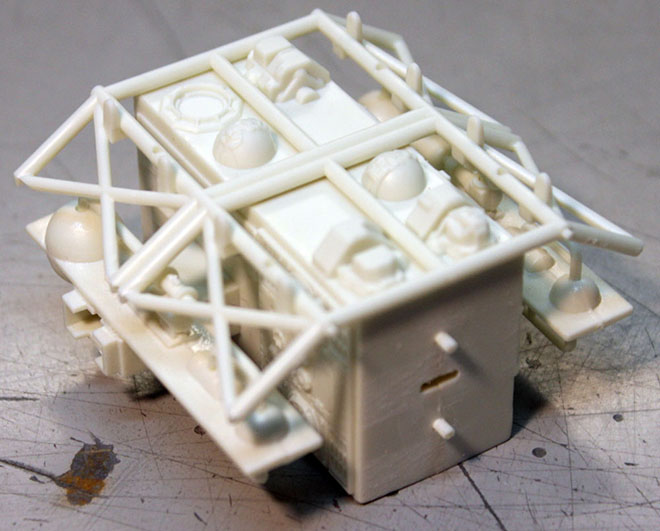
Next glue the cruciform section in place.
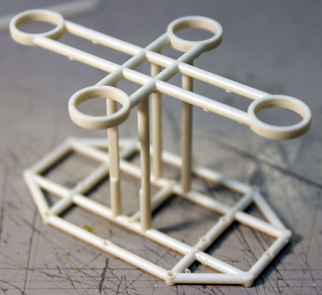
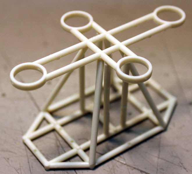
Then with the glue still soft, cement in the four angled braces as shown. Do two opposing corners first, then the other two. It’ll do a lot of wobbling around on you as you do this, but you will find that once all of the braces are in place everything will self-align. Put the unit down on the table as shown and press down gently on the center of the cruciform to weld everything together for a strong bond. Make sure the cruciform is not twisted in relation to the main frame when you sight straight down on it.
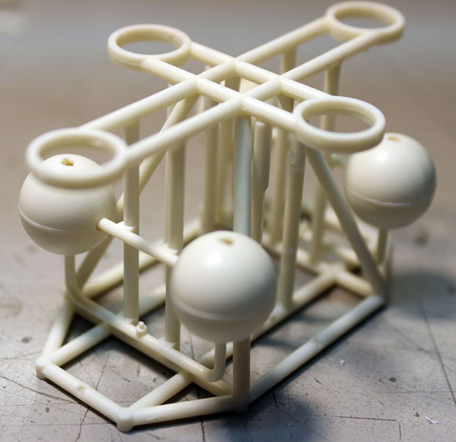
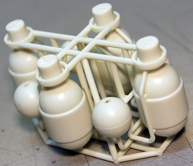
Next assemble the sphere halves onto the sphere frames and then glue those assemblies in place between the main frame and the cruciform as shown. It’s easier to put the end onto the main frame first, then swing it up into place in the cruciform. You can flex the parts just enough to allow the pins to clear.
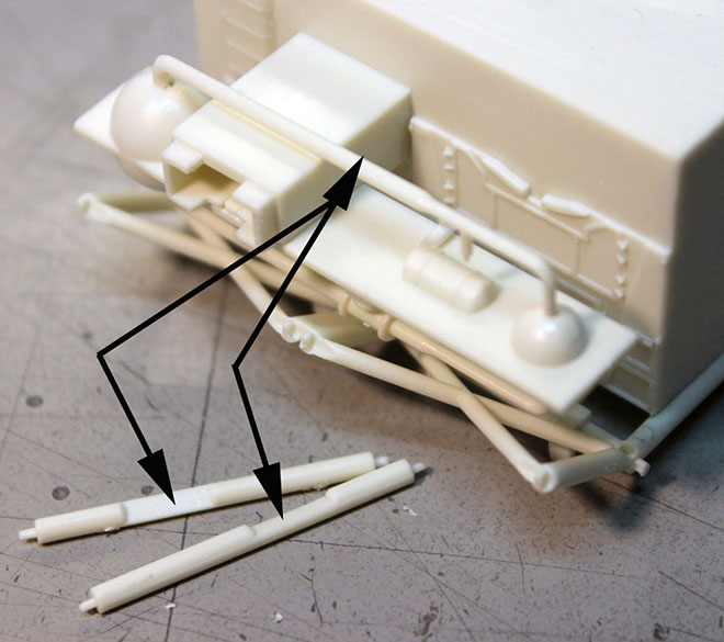
Now, grab the longest of the squiggly pipe parts and glue them to the main frame as shown exactly in the picture. It’s the same on both sides. Tweezers will help a lot here. Pay close attention to the orientation of the parts, exactly as shown. Just glue the center down on the pin in the middle and make sure you sight it all up and keep the tubes level and parallel as shown. Allow to dry.
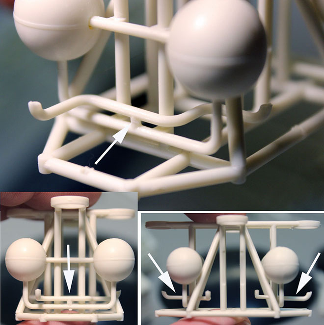
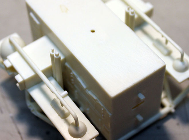
Now you can put the main engine bottles into place. Push the back ends through the cruciform hoops first, then swing the front pins down and cement them to the main frame. Line up the piping so they fit with the previously placed squiggly pipe sections and glue the joints together.
Glue on the remaining piping that goes from the spheres to the back of the engine bottles.
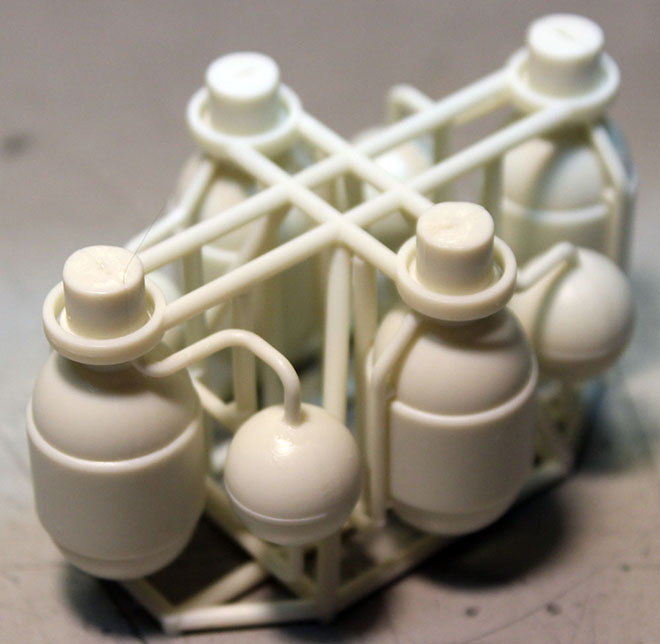
Now you can also put in the center pipe that goes from the center of the cruciform to the main frame. Make sure it is centered and seated as shown. You can offer the assembly up to the rear of the cage assembly to make sure it all lines up before the glue dries.
And you’re done that section! That wasn’t so hard, was it? You can either glue it to the back of the cage assembly now, or you can leave it of and paint it all as a unit. Enjoy! More to follow…
Space: 1999 Models: New 1/72 scale Eagle kit Pt. 4
Continuing our guest series reviewing the new 1/72 Eagle test shots. Enjoy!
Getting Cagey About This Build.
By E. James Small
Here we go again folks. Another update on the 1/72 scale Eagle build.
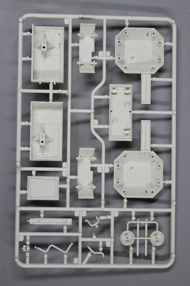
This one is pretty simple despite the complicated way I’m describing it. Just showing my personal recommendations of the building sequence for the cages on the model. In my opinion this is the best way.
Procedure is the same for both end cages of the model.
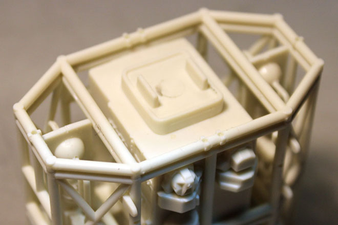
First, assemble the 4-part companionway “box” sections with doors and 2-part shelves. Make sure you get the roof oriented front to rear as shown and door oriented properly top and bottom!!!When you glue on the shelves, make sure you get them as close as possible to the box structure and make sure they are dead on parallel with it to make sure the rest of the cage frame structure will glue properly in place.
Next, glue on the TOP cage structure as shown. Make sure it all stays perfectly parallel. Make sure you glue it on the right way ‘round too! Note that the little locator pins on the end of the longitudinal pipes go to the same end as the slotted end of the box, opposite the doorway as shown!
Next get the notched uprights on either side of the boxes as shown and glue the ends ONLY to the top cage section. Tweezers or fine pliers will help a lot in this operation. Make sure the notched sections of the pipe go flat against the shoulder pod plug-in sections as shown by the arrows but don’t glue the flats in place yet!
Glue the non-notched uprights next to them.
Next, you will carefully orient the bottom cage section (pay attention to those longitudinal pipe end pins again!) and line up the ends of those pipes to the holes and glue in place at those joints only. Yes, it’s a little sloppy right now and things can still move but that’s what we want at this point. We want to allow for a bit of movement until we get the side frames in place as this will assure proper alignment.
Next glue the end uprights in place by carefully flexing the top and bottom frames to allow the pins to be inserted.
Now you can glue the side frames to the top and bottom frames. Once those are in place and carefully aligned you can use a long brush and liquid cement to glue the rest (flats on uprights and bottom frames to boxes) in place.
Lastly you can glue the front octagonal frame and nosecone mount in place.
You can test fit it of course, and it is recommended before the frame glue dries, but DO NOT glue on the REAR octagonal engine frame yet! You will need that separate for when you build the engine section. That frame will be put in place only after the engine section is built! More to follow….
Space: 1999 Models: New 1/72 scale Eagle kit Pt. 3
Continuing our guest series reviewing the new 1/72 Eagle test shots.
Let’s Prep for the Future!
By E. James Small
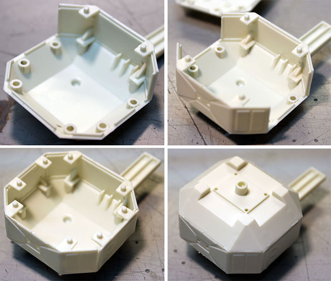
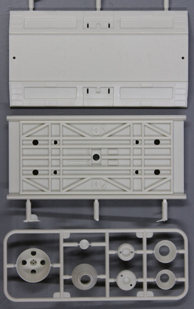
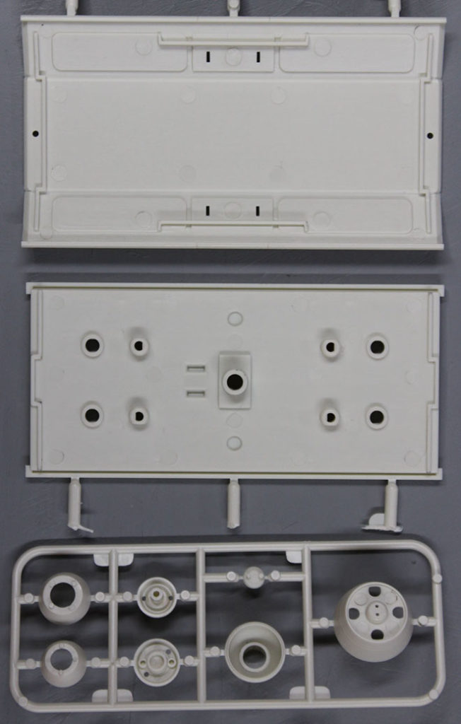
Ok folks, when you build your new 1/72 scale Eagle, you’re going to want to think ahead. What if you need to add something later? What if a cool new optional accessory like… oh, I don’t know… say, a side booster set or something similar gets put on the market? You’ll want to access the inside of the passenger pod so that such an option can be attached with magnets, so you don’t have to glue those accessories to the pod permanently. Access to the inside will allow you to do so at a later date. Therefore, when you build the passenger pod on your Eagle, you might want to do it in the sequence shown…. (same goes for the 22” model too, frankly speaking!)
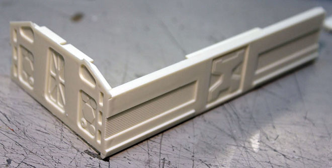
First assemble one side and end wall.
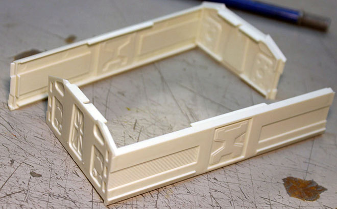
Then do the opposite two.
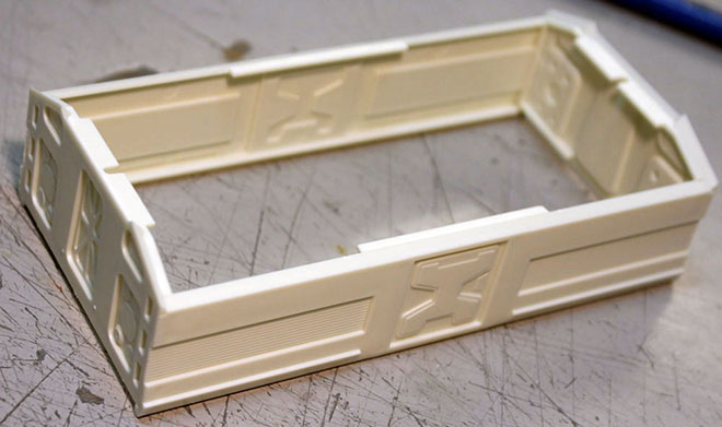
Then lastly add the roof.
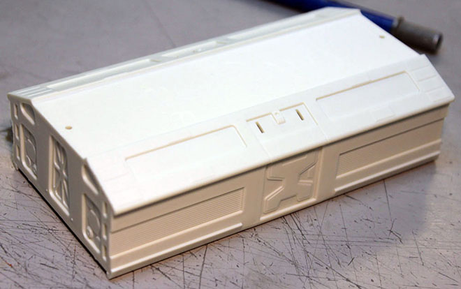
Sand down the seams as needed. (Hint: Leave those two little square ribbed bits that go above the door off until your model is painted… much easier to paint them black separately and add them to the pod after you have finished all your painting! That’s why they were made as separate parts, and why they are not shown here!)
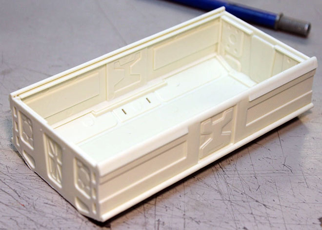
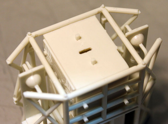
Put the floor on LAST! Why? well, before you put the floor on, you may want to consider allowing it to be removable so the inside can be accessed later as I mentioned above. You can do this by attaching the floor using magnets or screws. Yes, you’ll need to add something of your own design, such as gussets attached to the inside corners for the magnets and screws to mount to. So go ahead and devise your own way of making that floor non-permanent.
If you are careful when gluing your passenger pod walls together , you may find the floor to be a natural friction fit as well. so you may decide you don’t need magnets or screws, but don’t count on it. Friction fits are not always reliable.
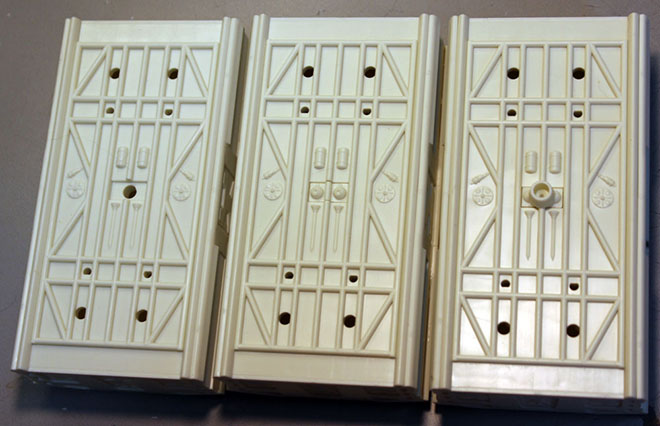
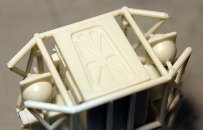
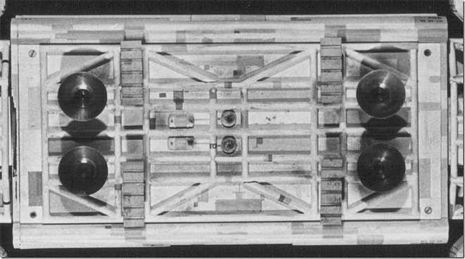
As you can see, the kit as it comes allows for the stand mount to be optional as well. By making the floor removable, that small centre bottom hatch can be more easily replaced if you want to swap them out as desired. See the three pods side by side? The hatches shown are most easily removed by pushing them out from the backside of the floor. By making the floor removable, you can make your model a lot more versatile! Heck, you could even get adventurous and put a lighting power supply and switch in there if you want to modify your model for lighting! So keep this in mind when you build your Eagle! Enjoy!
Space: 1999 Models: New 1/72 scale Eagle kit Pt. 2
Continuing our guest series reviewing the new 1/72 Eagle test shots.
Also, we have posted photos on our facebook page of every entry that was eligible for our award at Wonderfest USA last weekend. We also posted a short video of the four adult finalists.
Enjoy!
Developing a Spine in Today’s World.
By E. James Small
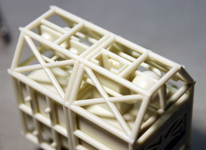
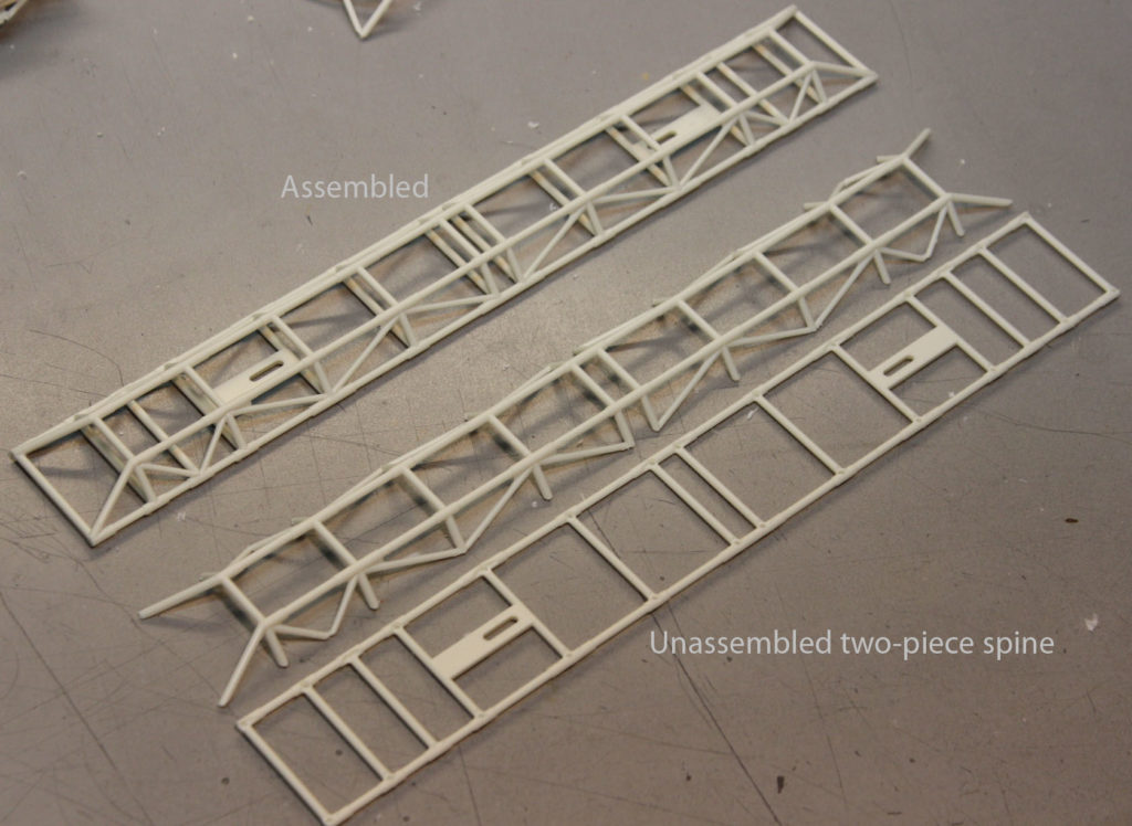
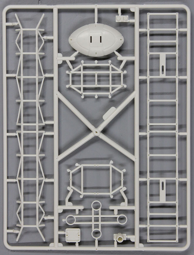
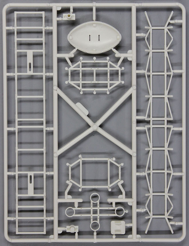
One of the things I personally worried and spent a lot of time thinking about when contemplating the shortcuts needed to take the fantastic MPC 22” Eagle and shrink it down to 1/72 scale was how the new model’s SPINE was going to be molded. We didn’t want it to look like previous versions made at similar scales that had flat backsides of the tubing and still be strong enough to support the finished model. Also it had to be ACCURATE in proportion as well as easy to build. Parts count and tooling real estate had to be kept to a minimum to keep costs as low as possible. Tooling draft, which means that the two halves of a solid steel mold must be able to be pulled apart without trapping plastic parts in undercuts that would otherwise provide full detail, has always been a problem for all injection kits. That standard had to be improved upon so that the new model would still represent the original HERO miniatures and not look like a cheap toy. Previous offerings of die cast and injection molded models and toys all had those problems. Therefore, how to do it better?
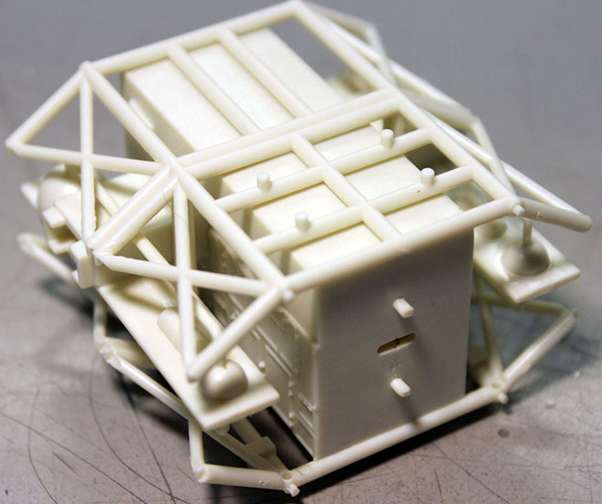
This is one of those times when I wish I could satisfy my personal ego and take credit for such a simple yet ingenious solution as shown in this picture.
Nope, can’t do it. I had nothing to do with it. The design credit goes entirely to Round 2’s graphic artist and product developer Jamie Hood! In fact it’s one of those Homer Simpson “DOH!” moments when Jamie showed me his idea and I thought to myself “DUH! Why the bloody hell was that never done before? It’s such an OBVIOUS solution to the problem! Why couldn’t I think of that? Why did nobody else think of that decades before?
And, no doubt, all of you reading this, now having seen it will also say the same thing and think; “Why would you do otherwise?”
OK, ask that question of everyone else who made an injection molded Eagle model. Let them wallow in the failure that has been overcome in this new kit! Get it? Yeah, easy to understand once you see it done, not so easy to come up with that simple solution if you’ve not already seen it! Jamie is fairly reticent to take credit for a lot of stuff he does, including the many illustrations he does on kits you do and don’t even know about, so I’m gonna do it for him. Everyone please give him a virtual round of applause for his work! He does a lot that nobody hears or reads about!
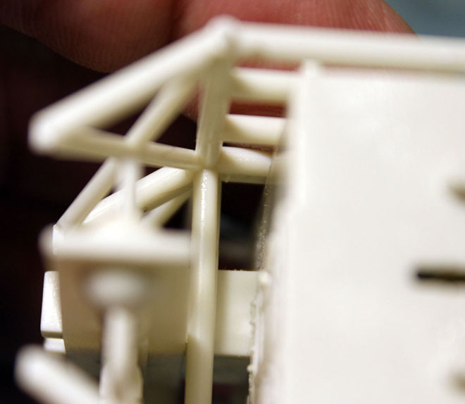
“OK”, you ask, “Why wasn’t that done on the 22” model”…? Well, even with Jamie’s ingenious design that even the factory didn’t figure out, there are some flaws on this smaller model that was overcome with more parts on the larger and more expensive version. You must understand the limitations of injection molding, especially the aforementioned draft. The worst of them is slight “webbing” around the tops of the triangular bracing at the top longerons of the spine. Yes, those are necessary molding shortcuts that are needed to keep parts count and tooling down for a smaller scale and lower cost kit. As a builder you can either ignore them or take the time with a #11 Xacto blade and carefully carve them out. The point is, the model will still look “right” whether you choose to do that cleaning up or not, as shown in the photo you see here. No significant cleanup was done in the examples shown.
Ladder and frame. That’s all there is to it. Now you see what it takes to develop a good solid spine in today’s plastic world!
Space: 1999 Models: New 1/72 scale Eagle kit Pt. 1
We hope sci-fi modelers had a good time this past weekend at Wonderfest USA 2019 or at least heard from friends that were there and saw their pictures, etc. We had a blast ourselves. We will post a report later this week, but first we are going to start a series of guest blogs by Jim Small focusing on our brand-new Space: 1999 1/72 scale Eagle Transporter. It grabbed a lot of attention from everyone who stopped by our booth. We sent a set of test shots to Jim just before leaving for the show and we didn’t want to hold anything back. So here we go…
Eagle Hatchling!
By E. James Small
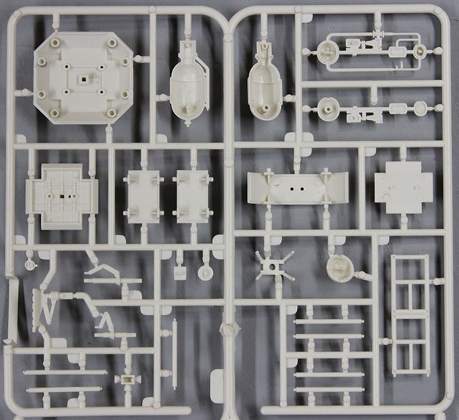
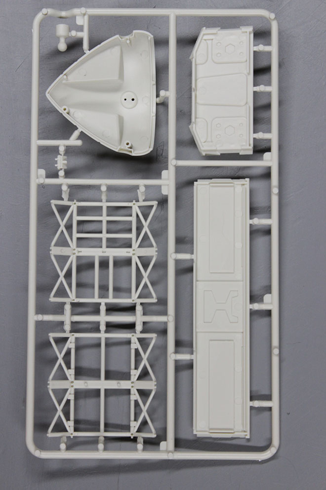
As you all know by now, Round 2 has recently announced their new release of a proper 1/72nd scale Eagle kit. At about 14” long when finished, this kit is perfect for people who don’t have the room to display the larger 22” model, and is made in the popular model aircraft scale. Here is an up-close and personal look at the test shot sprues of the new kit.
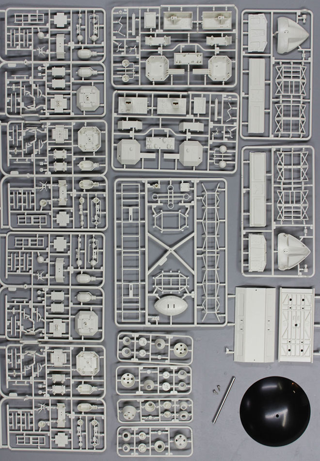
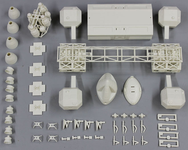
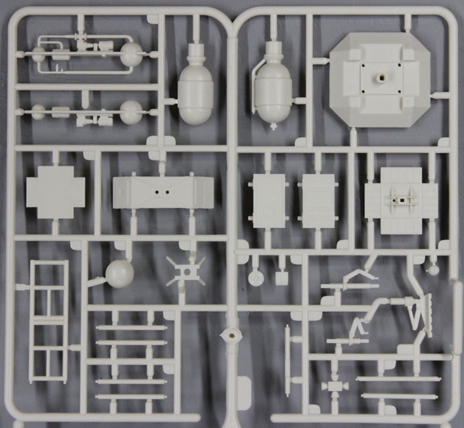
The first pic shows the entire contents of the kit minus the decal sheet and instructions which are yet to be developed. The rest of the pictures show both sides of each type of sprue contained in the kit. Obviously most are repeated. This kit has all the details present in the 22” kit with the added bonus of being able to be mounted on a stand via a replaceable plug on the bottom of the passenger pod. Those who wish to forego the stand can cover the mount with a hatch detailed to match the hardware that is normally in that area. Also like the 22” big brother, the passenger pod is affixed to the spine with screws so it remains removable. Gosh… I wonder if maybe other pod versions will be made available? [Don’t get me in trouble here, Jim. -Jamie] Windows for the passenger pod and nosecone will be represented by decals. Fun fact: on the original 44” studio Eagle models, the Passenger Pod windows were actually not clear but painted over black, so decaled windows in this case are perfectly authentic. Because of its size, articulated landing gear oleos struts were not possible, but you have the option of two positions of struts: landed/collapsed or extended/flying positions.
Enjoy this first detailed look at all the great parts contained in this fantastic new kit!
Heck of a far cry from that old 1970’s version, eh? This is the kit we’d always wished had been done at the time!