Recommended Sites


Archive for the ‘Polar Lights’ Category
Warp Drive & Transporters: How ‘Star Trek’ Technology Works
The original “Star Trek” television series featured technology that had first appeared decades earlier in science fiction stories. Pulp heroes had been wielding ray guns, flying faster than light and teleporting from place to place since the 1930s. But perhaps the true inspiration of Star Trek’s superscience is the revolutionary physics discoveries of the early 20th century. Relativity, discovered by Albert Einstein and quantum physics, pioneered by Max Planck revealed a universe far different than ordinary human experience might suggest.
Although Einstein’s theory forbids matter to accelerate past the speed of light, the demands of sci-fi storytelling require that people be able to travel between the stars in a reasonable amount of time, usually hours, or at most, days. Enter the space warp drive , or as it was called in “Star Trek’s” pilot episode, “hyperdrive.”
Warp drive in Star Trek works by annihilating matter (in the form of deuterium, a kind of hydrogen gas) and antimatter in a fusion reaction mediated by dilithium crystals. This produces the enormous power required to warp space-time and drive the ship faster than light.
To see more visit:
http://www.space.com/21201-star-trek-technology-explained-infographic.html
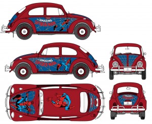
Spider-Man VW Beetle
Two all time classics join forces as Polar Lights presents Marvel Comics’ Spider-Man VW Beetle. This intricately detailed 1:24 scale snap-together kit features Spider-Man stickers to appeal to young modelers and several optional parts for the VW modeling enthusiast. Part options include steering wheels, bucket seats, bumpers, mirrors, exhaust systems, wheels and more. The hood and trunk open to show the spare tire and complete engine assembly.
Polar Lights Models: Thor box art
Although we just announced our upcoming Marvel Comics Thor model kit recently at Wonderfest, the kit has been in the works for some time. The Thor box art was just turned in this past week, so we figured we would show off a preview.
The first step in starting a kit like this is getting control drawings or turnaround drawings done of the model so that we can get the idea of the kit submitted to the licensor and also supply a clear vision of the kit to the sculptor. I did the drawings myself for the Wolverine kit. (I just couldn’t let the opportunity pass me by) I wasn’t quite as attached to Thor as a character. He has always been around as one of the key characters in the Marvel universe and an Avenger of course. My heart was always with the X-Men though. I knew what he was all about, knew his background and powers etc., but I wasn’t sure about the details and idiosyncrasies of the character. I needed to find someone that I knew I could bounce my overall idea off of and would be able to flesh it out form there. Joe Jusko came to mind. Though he is known as a painter, he had done a few pieces of line art for us for our Captain Action line so I figured I would run the job past him. As it turned out not only was he familiar with the character, he was a huge fan having read the Jack Kirby and John Buscema comics from the “Silver” and “Bronze” age of comics. Not only that, he also had a fondness for the old superhero models that we are all familiar with and was excited by the opportunity to turn one of his favorite characters into a kit.
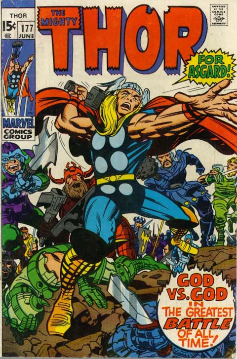
So, I explained my idea of trying to translate one of Kirby’s classic poses into a kit that would feature a modern, realistic but stylized sensibility. The one thing I was hung up on was what to do for the base. I like a figure to tell a story similar to the old Spider-man kit. Joe suggested a broken rainbow bridge along with some rubble and Thor-centric accouterments. As long as we could make sense of the goofy-footed Kirby-esque stance I was up for anything. He came back with an awesome drawing of everything we had discussed. I had to plan on editing it down a bit due to concerns for the cost, but for the most part, it was exactly what we needed.
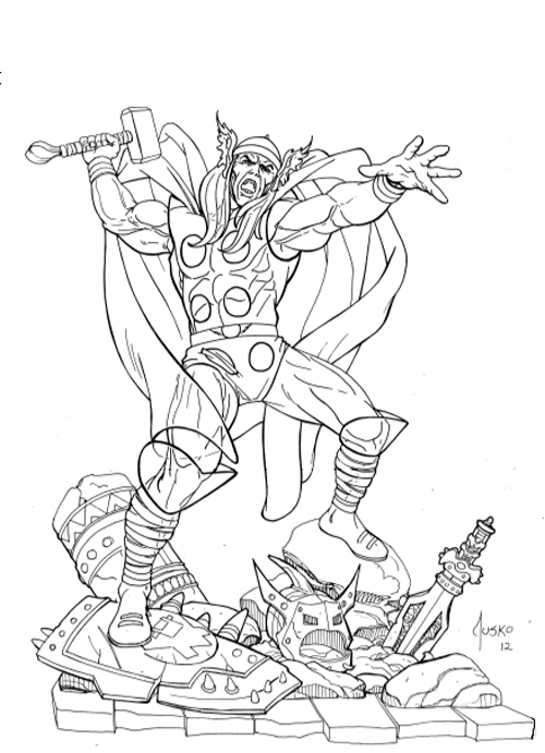
Of course Joe’s next question was “any chance I could do the box art?” After some quick negotiations, we were able to come to terms to allow him to do just that. The exact pose he had drawn actually fit our established figure box layout quite well. So we decided to just keep working with that angle. The question then became, “Okay, what’s in the background?” Of course the remainder of the rainbow bridge and Asgaard of course, but I threw a bit of a monkey wrench into the works when I brought up the idea of the box turn reveal of a bad guy. I had used the same approach for the MPC Hulk & Spider-man kits and in a more overt way on Wolverine. Joe figured out a way to incorporate a fallen storm giant. Again, I trusted the Thor fans intuition and let him run with it.
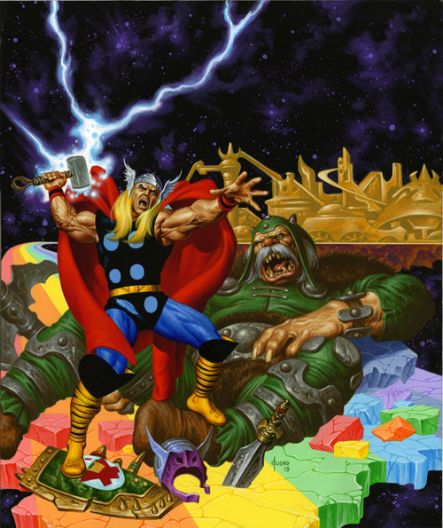
I think the end result turned out great and I was glad to have such an established and respected artist like Joe. I also feel fortunate to have found that he was a true Thor fan and was able to contribute to a kit of one of his favorite characters.
All images subject to licensor approval.
The 4-H Car ….Assembly
- Before gluing parts together, always ensure that the contact points are clean and that the parts fit well. When applying the plastic cement, only apply to one of the parts. An excessive amount of plastic cement will not only prolong or prevent proper adhesion, but may also melt and deform the parts. Plastic cement must always be used as conservatively as possible. When gluing clear parts, such as windows or canopies, try to avoid plastic cement. This is because plastic cement can “fog” clear plastic even in areas where not directly applied. For clear parts, use white glue.
- Gaps between parts may become apparent after assembly. To remove a gap that is too large to overlook, it may become necessary to separate the parts, adjust their fit, and re-adhere. Another option is to fill the gap with modeling putty, or another substance which dries to hardness and can be smoothed and painted over. When applying putty, only the smallest amount is required. An excessive amount will be difficult to remove later and in the case of clear parts, may be impossible to remove without evident damage to the part beneath. Follow the instructions on the packaging and use a plastic tool to apply the putty, so as not to scratch the model.
- If an assembled part is not adhering properly in some places, it may not be necessary to separate the parts and re-adhere. Another option is to use a liquid plastic cement to re-adhere the parts. By applying a small amount of liquid glue to the outside of the gap, the glue is drawn into the gap by capillary action. It is important not to apply too much glue, for the reasons above, but also because too much glue may remain outside the gap and dry to hard, malformed bubbles. In general, less than a drop will suffice. When the glue has been applied, hold the parts firmly together until proper adhesion is assured.
Once two parts are glued together, it may be necessary to clamp them together until the glue sets. This may be done by holding the two parts firmly together with your hands, but you may also use a variety of tools to do the same job. Elastic bands, clothespins, plastic clamps, tape, and wire are all suitable materials. When applying the clamps, make sure that the pressure exerted on the parts is great enough to keep the parts together, but not nearly enough to deform or break them. Also make sure that whatever clamp you choose to use will not scratch the plastic.
Whether you are a competitive modeler (contest, 4-H, Boy Scouts, etc…) or building for fun the following links offer some great tips and tricks to help you.
http://www.ndsu.edu/fileadmin/4h/FamilyConsumerScience/FE101.pdf
http://www.scaleautomag.com/
Here we are assembling the engine. He used most of the parts from the Stingaree model, he choose to use use the larger exhaust headers found in the Royal Rail model to customize this model. Here he is trying to hold them in place while they dry.
Polar Lights models: Wonderfest is right around the corner
One of my personal highlights each year continues to be the annual Wonderfest show in Louisville, KY. This year’s show is coming up the weekend of May 18 & 19 and it seems to be shaping up to be another great one. Seeing all of the great product available and seeing the work of all of the great modelers out there is a rare treat. Most of all though, I look forward to seeing all of the familiar faces and the chance we get to have to talk about our kits, the hobby and what you guys think.
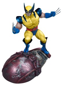
Even though we won’t be unveiling big news like the 1:350 TOS Enterprise, there will still be tons to talk about. We look forward to showing off our brand new buildups of our 1:144 C-57D, Robby & Altaira, Wolverine, the U.S.S. Enterprise bridge set and plenty more. We’ll give some info on development of the Galileo, Superman and all of the other all-new model kits we have brewing. We’ll have some surprising licensing announcements including hints at our plans for the ALIEN license. As always, we’ll have our annual survey ready to fill out to supply us with your feedback. We’ll be sure to fill in everyone that misses the show with our usual follow up youtube video of our booth and announcements.
We look forward to seeing everyone at the show!
http://www.autoworldstore.com/SearchResults.asp?Search=wolverine&Submit=Search
Polar Lights Model Kits- Robby the Robot Returns
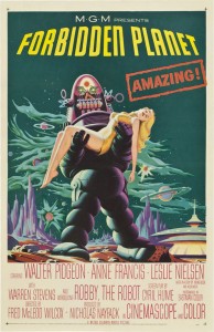
We announced our intention at Wonderfest last year to do give our Robby the Robot model kit a fresh spin to give a 3D representation of the iconic Forbidden Planet movie poster. So this June Robby the Robot returns as the Robby the Robot Movie Poster Edition. It seemed simple enough to take our existing Robby kit, add on a few new parts and boom; we would be off to the races. As usual, there really is no such thing as an “easy” task.
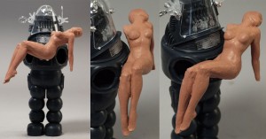
We knew we would need work with the parts we already have, so we knew we couldn’t work digitally in this case. We started out by hiring Tim Bruckner to tackle the sculpting duties. Tim has sculpted many licensed collectible statues and action figures. The difficulty before him was to use hard parts that we wanted to avoid retooling like Robby’s head and body and sculpt the needed Altaira figure along with new arms, legs and base for Robby. On top of that, he needed to stay as close as possible to the main reference, the movie poster, and translate a 2D painting into 3D that keeps all of the human body parts in proper proportion and get it to seat correctly on Robby. Our licensing agreement does not include likeness rights so we knew we needed to make sure the face stuck closely to the poster, and looked nothing like the actress. The Robby you see on the poster also strays a bit from the look of the real character. Ultimately we found that we needed to find that elusive sweet spot between the poster and what the “real” thing should look like in 3D. So with the parameters of our mission set before us, Tim began sculpting.
The first hurdle that was encountered was the fact that the movie poster shows no trace of Altaira’s right arm. It really isn’t something you notice when you look at it, because the mass of Robby’s body lends enough cover to make us assume that it must be there somewhere. Robby’s shoulder dome restricts the notion that the arm could drop straight down like the left one does. That left two possibilities. A) Her arm was tucked in between Altaira’s and Robby’s bodies, but her right hand could not land in her lap which would have been the natural position for it. B) Her arm had somehow landed up resting back over Robby’s shoulder. (Think it through, if Robby was lifting her unconscious body, how could her shoulder have ended up there?) We decided to proceed with notion A and see where that would lead us.
While we were figuring that out, creating Robby’s new wide stance was a simpler proposition. Old kit parts were utilized to create a mockup of the new part. They were cast up into solid resin soon enough.
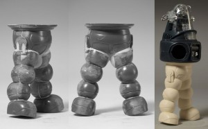
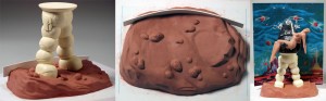
With the legs in hand, the base was begun. We wanted the new base to represent the rocky alien ground that he was standing on in the poster. We also wanted to finish off the full poster effect by including a cardboard backdrop that supplies the background. So a channel was implemented to situate the backdrop. We left it to the factory to supply some gravel/soil texture to the piece after tooling was cut.
Getting back to the figure, another problem that arose during the process is that in the illustration, Altaira isn’t really resting on Robby’s arm. The right side of her torso is raised so that we can see it, but she is clearly being held up by Robby’s hand on her left side. This left a gaping hole in the model. We played with the idea that her right arm had been caught up under her and that was what was holding her up.
Building our model for the fair…
Well it is that time of year again and we are just starting our fair projects at home. Unfortunately we live in a 3rd floor apartment, which makes painting both inside and outside difficult. To minimize fumes and mess I began to look for options for building a miniature spray booth. I am not endorsing either of these, because I have not completed it yet, but I found 2 sets of instructions for completing this project.
It looks like the materials I will need to complete this project are
1) Plastic Storage Crate or Similar Size Cardboard Box depending on which set of instructions you choose..mine will depend on whichever box I can find.
2) An extractor fan – the second set of instructions uses the exhaust hood from a stove. This one seems simplest.
3) Flexible hose – like for a dryer vent
- Full instructions are available on the individual pages.
http://www.militarymodelling.com/news/article/homemade-spray-booth/3661/
http://www.interlog.com/~ask/scale/tips/booth.htm
This second set also includes some great ideas for cleaning, painting, and preparing your model. Once we get started I will share our photos.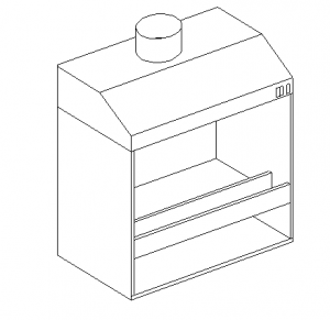
Polar Lights: Shedding Light On An Old Enterprise
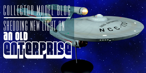
We have received some questions about the installation of the new lighting sets for the 1:350 scale U.S.S. Enterprise model kits so we put together a quick tutorial video that is available through our YouTube channel and our Collector Model Blog. Polar Lights brand manager, Jamie Hood, shows step-by-step how the lights should be installed into the model. This video covers some of the trickier spots that a modeler may encounter as well as some helpful hints to ease the assembly of either MKA005 Deluxe Accessory Set and MKA007 Lighting Kit. As with any of our model kits, we recommend reading all of the instructions completely before you begin any project, but this video should grant a great insight about the installation before the project is begun.
We’ve seen some excellent buildups with the lights installed. We hope this video assists those that have been holding back from lighting their builds. Enjoy!
Polar Lights Model Kits: Back to Back to the Future
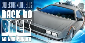
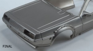
Polar Light recently decided it was time to get back to Back to the Future and bring back the 1:25 scale Time Machine this summer. We recently inspected a copy of the previous release examine the faux “stainless steel” finish was already present on the model’s body. After discussing with the factory about the possibility of repeating this finish on the new release, we were offered a slew of options to explore. (Be sure to click on the pics for close-up views)
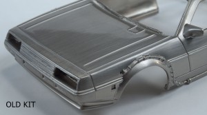
The original kit had what would looks to be a standard chromed body that had been sanded with steel wool before it had been gloss coated. While the look was a valiant and notable effort, it looked very toy-like. The sanded lines were too big and noticeable to be considered true to the scale and the gloss coat was excessive.
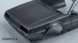
Our factory offered a few alternatives from various sources that used a couple different techniques for applying the chrome and sanding.
Example A looked the best. I had a nice fine and evenly distributed sanded finish, but the color was a bit dark more like pewter than silver. A couple of the highest details also had a bit of a bronze color showing through. This was the base color of the plastic. I assume this example had been used on another faux-pewter looking product as the crevasses looked darker as if it was antiqued.
Example B looked similar to A, but it lacked the sanded lines. The finish was easy to mar and discolor with fingerprints. A significant amount of rubbing removed them, but the finish maintained a blotchy look overall.
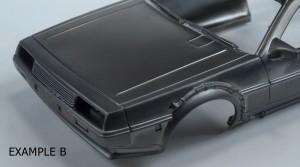
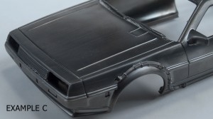
Example C looked like B, but had sanded lines added back in. They weren’t as evenly applied or as apparent as A. Some areas were missed and some were a bit heavy-handed.
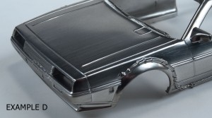
Example D looked like a departure form the first three. It looked like it went back to the chrome/silver look of the old one. In this case, the gloss level wasn’t as high, but the sand lines looked like they had been applied with coarser grit. There weren’t as many lines, but the ones that were there were too prominent.
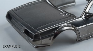
Example E also looked similar to the old kit, but didn’t have as high of a gloss level finish. The example came with a note saying “process warps body. Advise not to use.” And the body was warped (wider than it should have been) so we won’t be using this one.
This left us with a quandary. All told the quality and finish of example A was by far the best looking, but it was too dark. So we asked if it could be lightened to look more like silver. The result looked perfect… well, as perfect as we could expect for a 1:25 scale kit. The color is pretty spot on and the sanded lines are nice and even and aren’t too deep. It doesn’t use a heavy clear coat so all of the details show up nicely too.
We think this change is a significant improvement over the last release. Keep an eye out for the kit coming in June.
GLUING A SNAP KIT IS A SNAP! …Part 3
Continued…
Puny Human Pin Hulk?
Whether you use the base that comes with the Hulk or you’re planning to use something different, I suggest you plan on pinning the big guy. Pinning isn’t difficult and will make your model more stable on its feet. It starts by filling the hollow foot assemblies with a solid material that will hold the mounting pins. I used epoxy putty that I pushed into the foot halves before I assembled them. The assembled feet could be filled with plaster of Paris just as well, but make sure all the water in the plaster has time to evaporate before you close up your model.
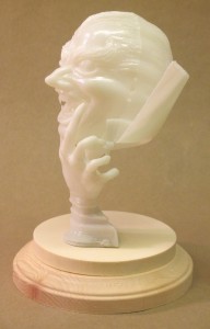
It hadn’t occurred to me to include pinning in this article when I was building my Hulk, so I will illustrate the procedure for pinning with another MPC snap-fit kit, the Vampire Glo-Head, Fig. 5. Round 2 has taken pains to make the model more stable than it was when originally issued, but I wanted to make sure it wouldn’t fall over at model contests. After the hand halves were joined, I filled the hollow interior with epoxy putty and sanded the bottom smooth.
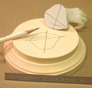
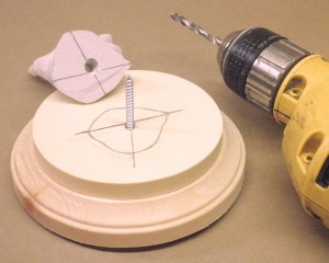
Then I needed to locate the hole in the resin and wood bases on which I would mount the model. This hole also had to line up with the epoxy plug in the base of the hand so it would sit in the proper position on the resin base. While I held the hand in position, I penciled four alignment marks around it, extending the marks onto the resin base. Then I connected the marks with the aid of a straightedge, locating the centers of the holes, Fig. 6. They were drilled into the hand and base; for this model, I used a big screw for the pin, Fig. 7. A section of sprue or a dowel would work also. I used this technique to pin Spider-man to his base as well.
If you’re reading this article in the first place, I presume you probably weren’t going to leave your Hulk unpainted. His upper body and feet assemblies were designed to be trapped by the trouser halves. It’s easy to paint the trouser parts and Hulk assemblies separately and then join them together.
The fit of the Hulk’s upper body to the top of his trousers isn’t the greatest, and the seams along the trouser halves are prominent. However, they appear where seams on real trousers do, so they don’t have to be eliminated for a realistic appearance. The pieces of the test shot I assembled had to be glued and clamped carefully to prevent them from coming apart. The gap between the Hulk’s torso and his trousers can be filled fairly easily (I brushed several layers of white glue in there) and the paint on the trousers touched up.
A Model of a Different Color
Everything I’ve had to say about gluing the snap-fit Incredible Hulk applies to the Amazing Spider-man – and all other snap-fit models, for that matter. Spidey was designed so the red and blue parts of his costume could be snapped together unpainted. The design itself is ingenious, but it makes life harder for the modeler who wants to assemble the model with glue.
I tried and failed to remove the mounting tabs from the hands and feet assemblies, thinking I could paint them separately from the body and attach them after painting. It would have been much easier to simply assemble Spider-man entirely (which I eventually did) and then paint him. This required a lot of masking, but the results were well worth the effort.
The hardest part was to get the red and blue sections to fit smoothly. I sort of cherry picked the areas where one section would have prominence over the other. And the usual seams reared their ugly heads under a coat of primer, Fig.8. I had to be careful not to fill the incised web pattern when filling gaps. Where I did fill the webbing, I tried to resculpt it with hobby knives and even a fine routing bit in a rotary tool – that proved unnecessary as we’ll see.
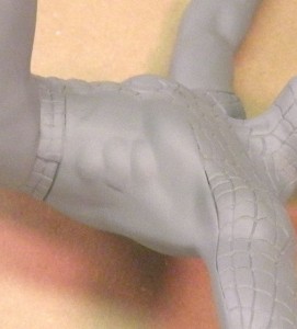
Painting the web pattern may seem daunting, but I found a few ways to make it easier. Over a good base of white primer, I painted the red areas of Spidey’s costume with an airbrush, using Testors Model Master Guard Red. This is a very bright red and dries to a gloss finish. To paint the webbing, I mixed a bit of liquid detergent with some Hunt’s black ink in a small cup. The soap broke the surface tension of the water-based ink so it wouldn’t puddle on the gloss red paint. Using a fine, pointed sable brush made it fairly easy to apply the ink into the incised webbing.
I found it best to plan ahead when applying the ink so that I could avoid grabbing a wet spot while holding the model. I began painting the back of Spidey’s boots – these were areas where I could practice painting the webbing without my mistakes being too noticeable (rubbing alcohol cleaned stray ink marks off the gloss red paint). I tended to hold the figure around the waist, so the next areas I painted were the arms, then the head, and finally the torso.
The ink dried rapidly; to prevent my finger oils from marring it or the red paint, I wore rubber gloves while I worked. I saw that the intensely black ink looked the same in the molded webbing as it did on any parts of it I had inscribed. Even flat surfaces where the webbing got filled looked okay; on its own the ink reinstated the detail very well.
Time to Celebrate!
– Because I’m done with this article and a couple of fine models. I was very impressed with the final appearance of these snap-fit kits. Their engineering made me take some different approaches to those I’d have made with glue kits, but the results were otherwise the same. I hope you enjoy building your models as much as I did mine.