Recommended Sites


Posts Tagged ‘MPC’
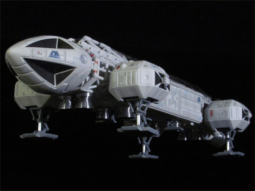
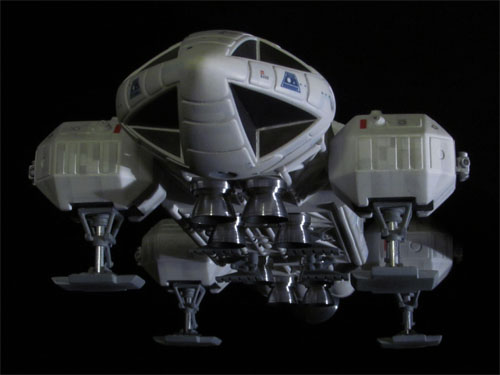
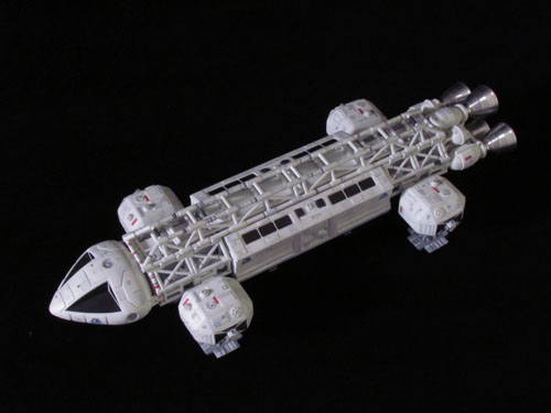
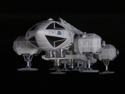
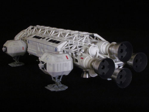
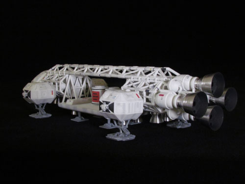
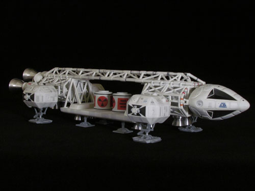
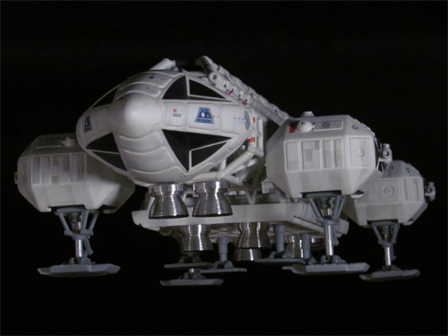
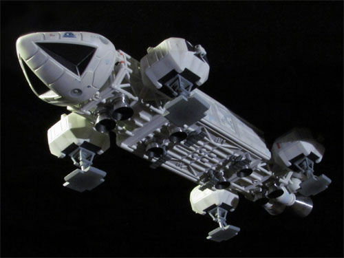
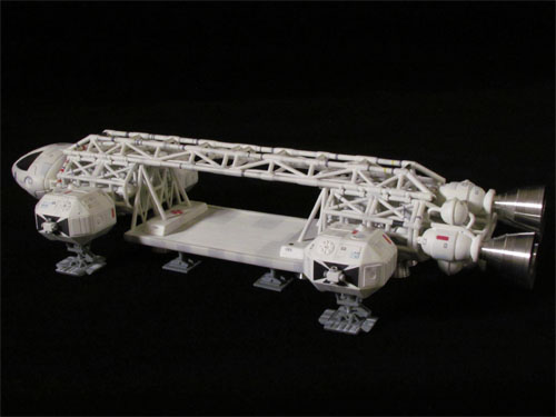
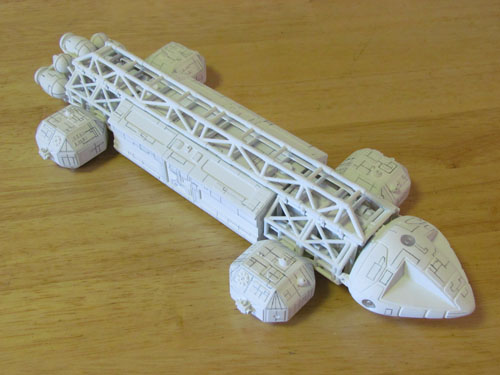
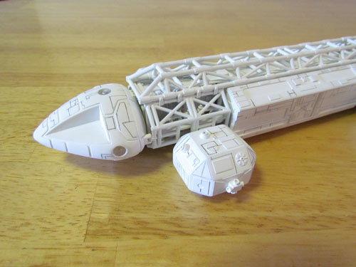
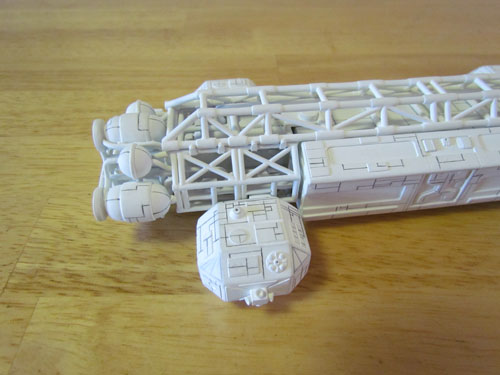
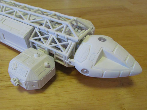
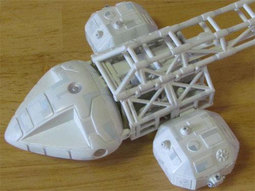
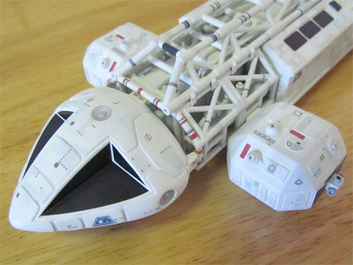
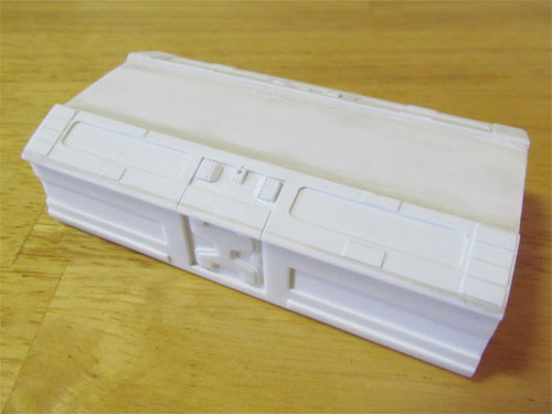
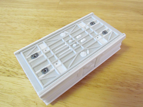
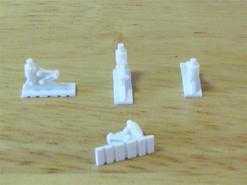
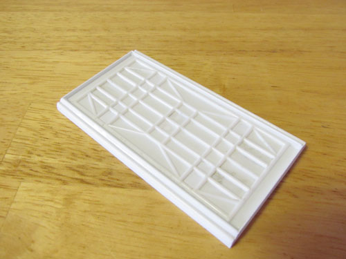
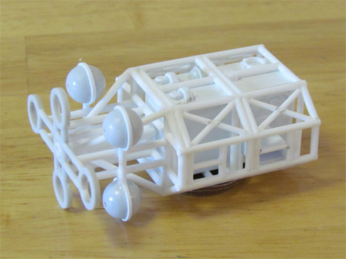
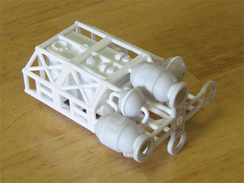
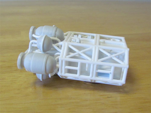
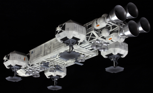
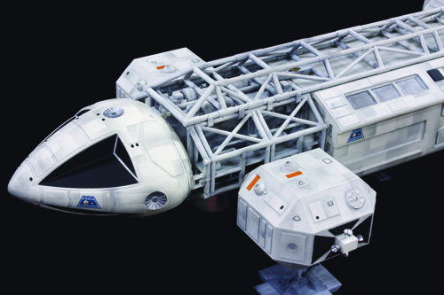
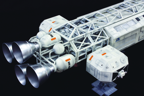
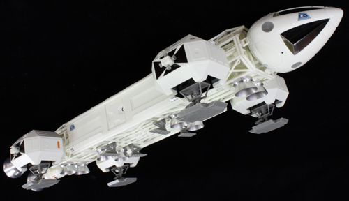
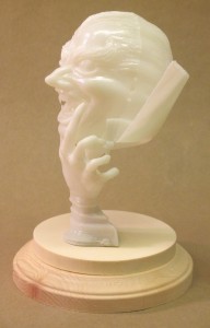
Transforming the Classic MPC Eagle Kit – Part 4
Here is the last of the articles from Michael Scarola showing his fabulous build of the 12″ MPC Eagle kit. We are generally just showing the finished model this time around. Thanks, Michael, for contributing this series.

I hope to post something soon showing our progress on the 1/2500 NX-01 coming in our anniversary boxed set coming later this year. Happy modeling.
Transforming the Classic MPC Eagle Kit – Part 3
Painting, Weathering, & Decals…
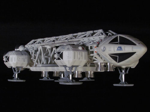
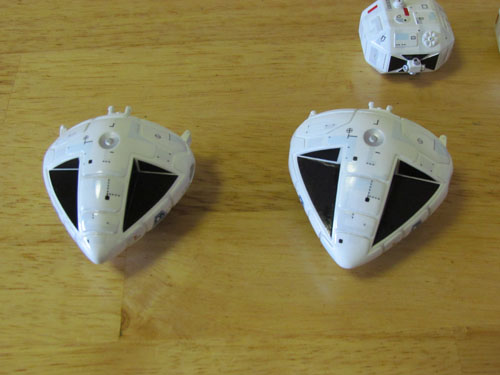
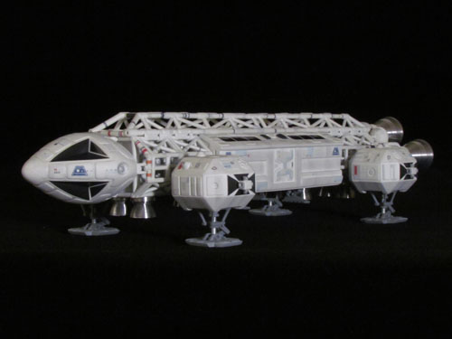
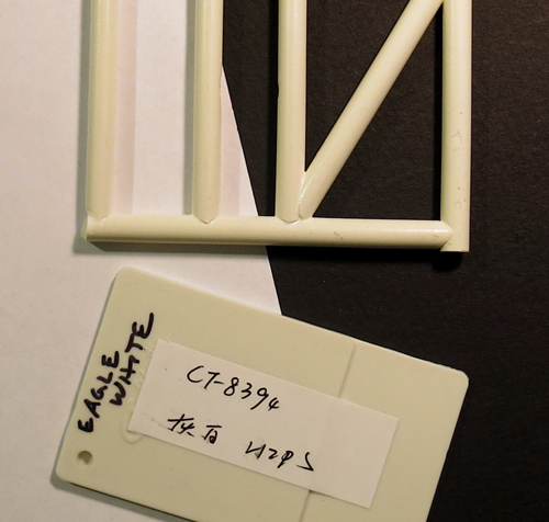
Not unlike the Star Trek original series Enterprise, the Eagle 1 studio model’s hull color has been a subject of debate among modelers. The paint/color that has become the most popular is an automotive paint, Ford Diamond White (FDW). The original Eagle 1, 44” studio model, was originally painted a plain white color but was later re-painted an off-white primer that’s the same shade as FDW.
For this build I wanted to replicate the look of the Eagle in mid season 1, when it had the various gray and blue panels as well as the panel lines drawn on. This seems to be a popular look as I’ve seen many Eagle replicas painted this way and happens to be my favorite look for the Eagle.
A friend sent me a sample of FDW that I used to mix the color using Testors Acryl hobby paint. After speaking with someone who works with automotive paint I found that a greenish-yellow pigment is used in the FDW formula to make the off- white shade. I added a couple of small drops of (Testors) Yellow Zinc Chromate to Flat White and it’s an almost exact match to the FDW color sample.
The color appears to have a creamy appearance with just a very small hint of green under various lighting conditions. With this mix worked out for the hull color all that was needed was to scale down the amount of Yellow Zinc Chromate I was adding to the white. For a larger Eagle, 44” or even 22”, FDW looks right but for this smaller 12” Eagle the off-white color looks better with just a bit less yellow in the mix.
I really wanted the small technical marking decals for this build so I decided to try and make some using the program Illustrator.
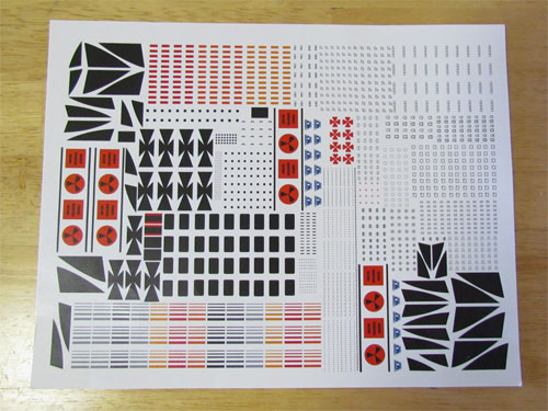
I’m still very new to using Illustrator but gave it a go. I studied reference images of the 44” Eagle 1 studio model and made the various markings as well as the windows and anti-glare panels for the resin CM and passenger pod. For the MPC kit’s CM I used the decals that came in the MPC 12” Eagle kit.
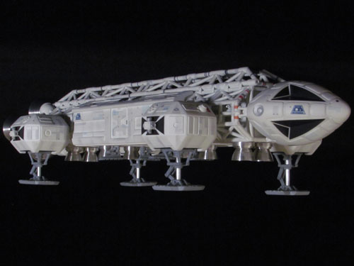
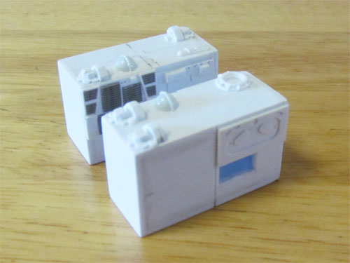
Now came the fun part… I sprayed the Eagle and all the various parts with the off-white hull color. After this, using reference pictures of the 44” studio model, I drew on all the panel lines with a pencil.
The hull color was then sprayed over the panel lines to blend them in to keep them more in scale.
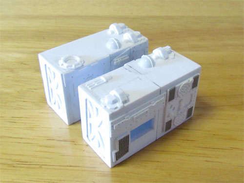
Using reference pictures, I started masking all the various gray and blue panels.
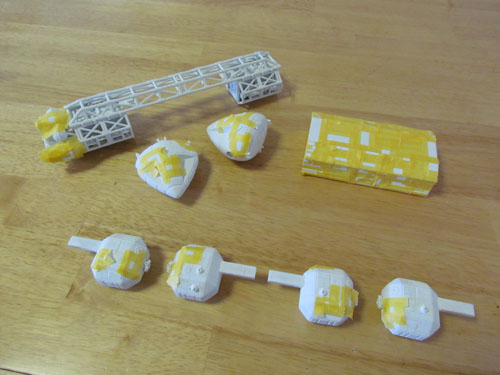
This image shows the gray and blue panels painted.
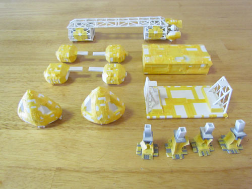
The decals were applied after the panels and small details were painted.
The model’s sections were weathered with dark gray pastel chalks and clear coated to seal it all in. I then sprayed a very thin, light mist coat of the off-white hull color over the decals for a more in scale look.
I sprayed Testors Create FX acrylic clear over the CM and passenger pod’s window decals, which I polished for a glass-like appearance. The windows were then masked when the final flat clear coat was applied. The landing gear was painted Testors Acryl Neutral Gray and the ‘toes’ on the main gear were masked and painted with the same Neutral Gray lightened with some Flat White.
Painting and applying the decals was almost as big a job as the build, well almost. Including all the small technical markings and windows, there are approximately 425 decals applied.
This was an extremely fun project that also gave me an opportunity to learn more about the original 44” Eagle 1 studio model along the way. I’m happy to have this one completed.
I’d like to thank Jamie Hood and everyone at Round 2 for giving me the opportunity to share this on their site.
Michael Scarola
Next time… a batch of beauty shots of Michael’s finished model. -JH
Transforming the Classic MPC Eagle Kit – Part 2
Here is the second in a series of articles by Michael Scarola showing the steps he has taken to accurize a 12″ MPC Eagle.
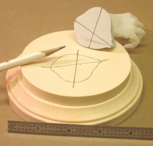
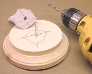
My Eagle 1 build continues…
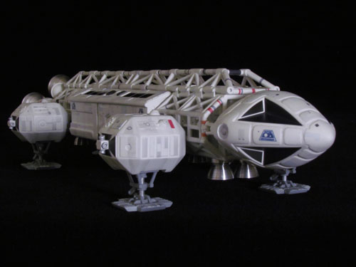
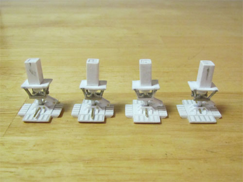
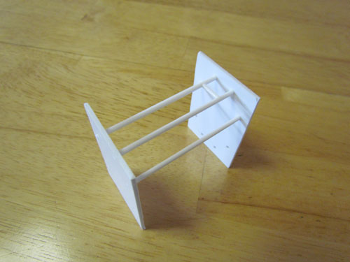
The 4 shelves that go inside the cages were each made from 2 pieces of .5 mm styrene sheet glued together.
The details were matched and scaled down from the Eagle 1 blueprints using 3.2 mm, 2.5 mm, 1.6 mm & .4 mm styrene rods as well as rounded sprue ends and the round domes from the ends of the nacelles of a Polar Lights 1/1000 TOS Enterprise kit.
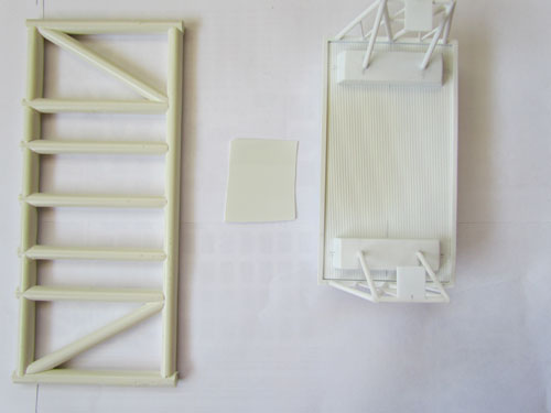
The MPC kit’s passenger pod has some nice detailing so I decided to use as much of it as possible. I started by scratch building new front and rear bulkheads. Three layers of sheet styrene were used with the various shapes and door details cut out…
…and Evergreen V-Groove sheet (.025” spacing, .020” thick) was glued into the side channels.
The top has neodymium magnets underneath for attachment to the spine. I made the eves with layered .5 mm sheet styrene and 2 mm round rod at the edge to give them the rounded shape.
The ‘Gemini’ kit details in the center of the eves were replicated with Evergreen Metal Siding (1 mm thick, .75 mm spacing) as well as the center details taken from the MPC kit’s passenger pod.
I removed the built in thrusters from the kit’s passenger pod bottom…
…to make way for a set of aluminum thrusters. The footpads were removed and replaced with ones I scratch built…
…and all missing pipes were replaced with 2 mm half round rods. Various styrene rods (3.2 mm, 1.6 mm, 1 mm, & .5 mm) and styrene sheet were used to scratch build the details.
A spare MPC passenger pod bottom piece…
…was used to scratch build a cargo pod. 2 mm and 1 mm styrene rods were used for the front and rear supports…
…and magnets were installed for connection to the spine. Evergreen Metal Siding (1 mm thick, .75 mm spacing) was used on the floor and 1 mm styrene sheet used for the rectangular ‘blocks’. The landing gear…
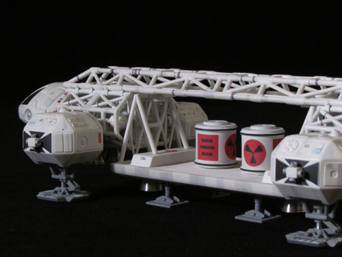
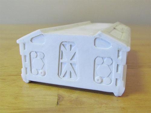
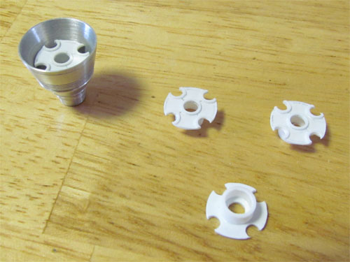
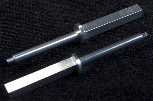
…is made up of various styrene tubes and rods (4 mm/3.2 mm tube and 2.5 mm rods) and 1 mm and .5 mm styrene sheet. Each foot is made to swivel with brass rod pins. A set of aluminum thrusters will be attached to the bottom when it’s all painted. I scratch built two Nuclear Waste Containers…
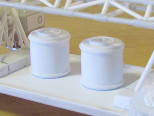
…using .5 mm and .3 mm sheet styrene glued around .5 mm top and bottom plates pieces. 11, 7.9 & 4 mm tubes were used for the top rings and 1 mm styrene strips for the raised bands.
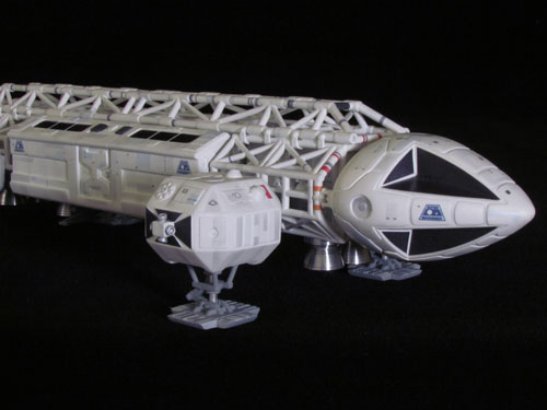
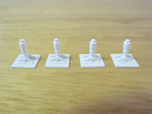
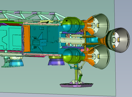
I used the kit’s shoulder pods but removed the raised details and shortened them a couple of millimeters. The details on the kit’s parts are more representative of the Eagle 2 studio model so I replaced them with details seen on Eagle 1.
I also attached prongs for connection to the cages so they simply plug in with no need for glue, just like the original Eagle 1 studio model.
The landing gear…
…was scratch built and made to retract with the use of aluminum tubes and the footpads are made to swivel. The footpads are the one’s from the MPC kit with the details removed and replaced with Eagle 1’s details.
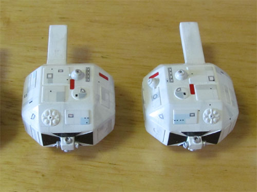
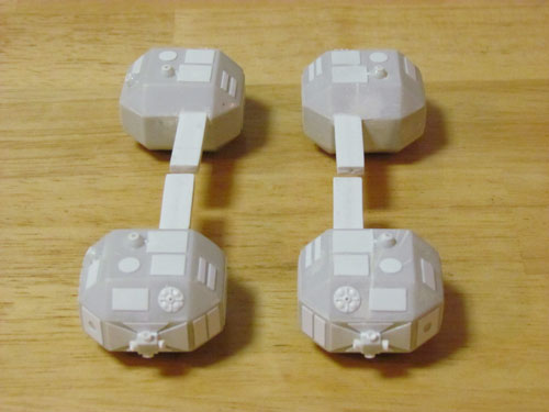
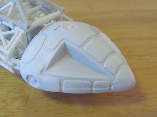
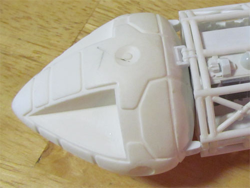
The MPC kit’s command module (CM) has a back piece made up of a couple of pieces of 1.5 mm styrene sheet with .3 mm styrene raised panels. 1 mm styrene was glued in between the top and bottom halves and 4 new brackets were added. The 4 sensor dishes were filled with putty and have 2 mm styrene rod glued into the centers to form the raised detail. The CM…
…is also removable with the use of magnets. In addition to the MPC kit’s CM I had a resin Small Art Works CM…
…in the stash that I decided to use as an alternate. I shortened the back by 5 mm’s and added the 4 brackets. A magnet was installed inside as I did with the MPC kit’s CM.
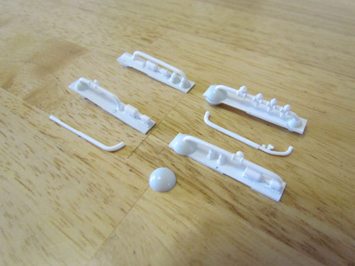
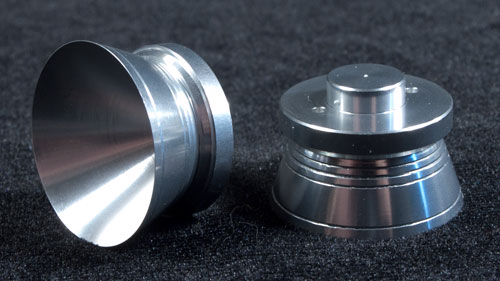
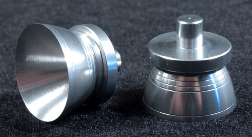
The last parts I had to make were the engine baffles, which were scratch built with .5 mm styrene and tubing for the raised details.
The Eagle has a unique hull color that involved doing some research which I’ll talk more about in the third and final installment as well as weathering and the decals…
Michael Scarola
Transforming the Classic MPC Eagle Kit – Part 1
As promised, here is the first in a series of articles by Michael Scarola showing the steps he has taken to accurize a 12″ MPC Eagle.
Transforming the Classic MPC Eagle Kit – Part 1
After all these years I finally got around to building a Space 1999 Eagle. The Eagle is a unique ship that actually looks like it could work as intended. I love its organic yet utilitarian design. For this build I started with an MPC Eagle and decided to make some modifications of the existing kit parts and also do some scratch building along the way. The MPC Eagle 1 kit is a classic that has been around since the TV show began and represents an Eagle nicely but does have some simplified sections and details that I felt I could improve upon. I wanted to use as much of the original kit parts as possible while attempting to make it accurate to the original Eagle 44” studio model.
The build…
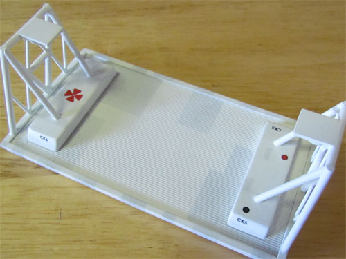
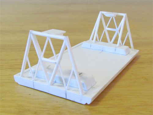
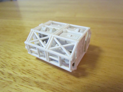
I used a WARP kit I have and access to a friend’s set of Daniel Prud’Homme Eagle blueprints as reference. I decided to start by scratch building the front and rear cage sections. I made a jig…
…out of a couple of pieces of 1.5 mm styrene sheet that helped keep everything straight and aligned. Using a round file I ‘fish mouthed’ the ends of the styrene rods so it would all fit together the same as the studio model. 2 mm styrene rods were used for the larger main rods and 1.6 mm rods for the smaller ones. This image shows one of the cage sections after removal from the jig.
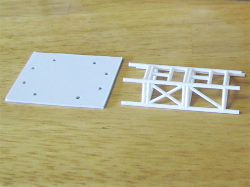
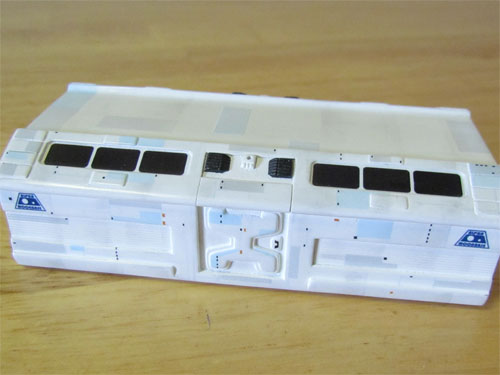
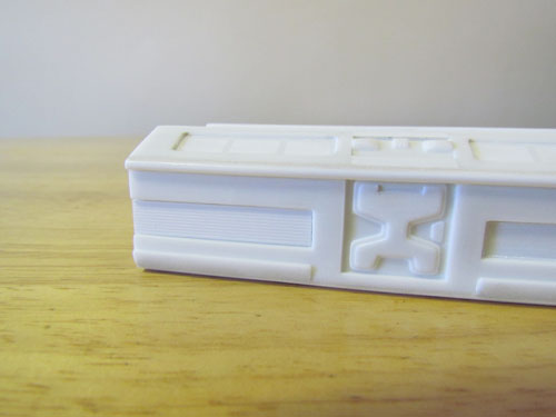
The MPC kit’s spine was shortened and narrowed and a flat file was used to re-shape the tubing since they are flat on the backsides. I replaced the inner supports with 2 mm and 1.6 mm styrene rods.
The corridors inside the spine were scratch built using 1.5 mm sheet styrene with channels made for attaching the shoulder pods. The doors at the ends of each corridor are pieces of .5 mm styrene layered to create the recesses.
The original 44” studio model’s corridor doors were drawn on but these doors match the ones on the passenger pod and look more realistic so I went with this approach.
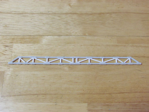
The details on the sides and tops of the corridors…
…were made from scaled down measurements taken from Daniel Prud’Homme’s Eagle 1 blueprints. I used .4 mm sheet styrene layered and other various sizes to create the side details that were actually kit tank parts on the original studio model. All the grill details are made from open grate platforms from Tichy Train Group. The details on top were a bit more challenging. On the studio model most of these consisted of model parts from Saturn V and Gemini kits. I layered .4 mm styrene for the ‘Saturn V’ end details and shaped the ends of sprues taken from a Polar Lights 1/1000 TOS Enterprise kit for the round ‘Gemini’ details. The Polar Lights 1/1000 TOS Enterprise kit has some nice large diameter sprues that I’ve used to scratch build parts on a few models I’ve worked on. That kit keeps on giving.
Now that the cages and corridors were completed I put them together using 2 mm diameter styrene rods that now completed the sections.
It was now time to move on to the rear of the Eagle’s frame. 2 mm styrene rods were used to make the framework that the cross section frame is attached to.
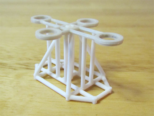
I used all 4 of the engine bottles and ‘balls’…
…as well as the rear cross frame from the MPC kit. I modified these parts a bit to more closely match the studio model. The bottles were shortened and new raised detail glued in between the ball halves. The piping, matched to the blueprints, was added to tie it all together.
In the next installment I’ll cover the building of the shoulder pods, landing gear, command module, passenger pod and the cargo pod…
Michael Scarola
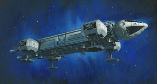
Space:1999 Eagle
A real quick post this week. We will be posting a new series next week featuring an accurized buildup of the MPC 12″ Eagle from Mike Scarola. Here is a sneak peek at his build.
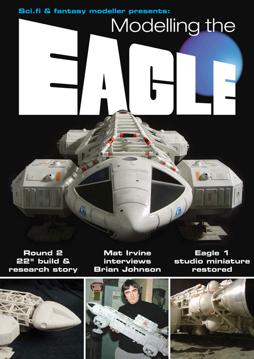
Also, our friends at Sci-Fi Fantasy Modeller had so much fun putting their Modelling the Eagle special last year, they are following that up with another great special this year. Here are the details…
September 13, 2016…
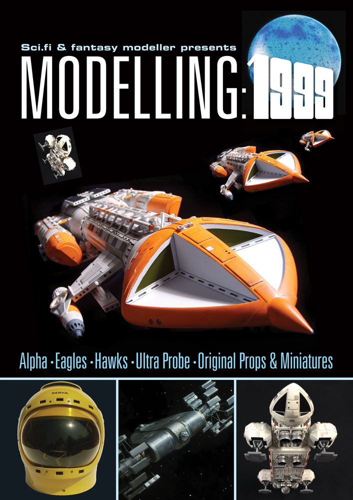
…A massive explosion of Space:1999 modelling rocks the world! Mark this date in your diary, because this is the day we publish Modelling:1999!
Featuring: * Alpha! * Eagles! * Hawks! * Swift! * Moon Buggies! * Alpha Tanks! * Ultra Probe! * Gwent! * Stun Gun! * Comlock! * Original studio miniatures! * Original studio spacesuit! * More Eagles! Plus much, much more!
Following the success of our recent Modelling the Eagle special, we are delighted to present an even more exciting large format Space:1999 modelling extravaganza featuring more pages and hundreds of exclusive photographs!
100 pages. A4 format.
To pre-order your copy now for immediate despatch on day of publication (mid-September) click here or visit www.scififantasymodeller.co.uk
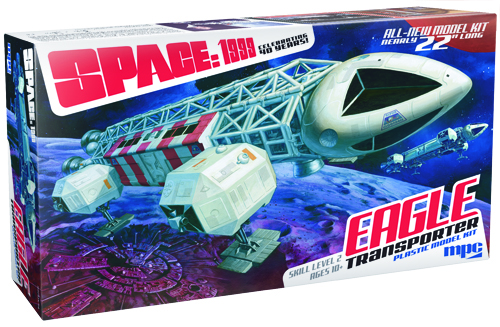
Space:1999 Models: 22″ Eagle update
UPDATE: Kits are due to ship from China by the end of November. No promises that they will land in modelers’ hands by Christmas, but may still reach many of you by the end of the year.
Nearly everyday I get an email or note requesting more info on our exciting new MPC Space:1999 Eagle kit. Quite a bit has happened since my last post and I’m overdue on an update. So here you go. Let’s see… where to start…
The parts- We’ve received two rounds of test shots. You may have seen comments from Jim Small or Jay Chladek online about the first set of those. I’ll admit I’m holding back a little bit on this one in order to save something for Sci-Fi Fantasy Modeler’s Eagle special where I’ll be contributing an article. Btw, to pre-order your copy click right here! I’m doing my best to balance the distribution of info between here and there.
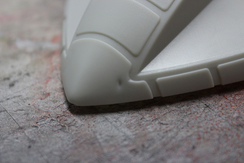
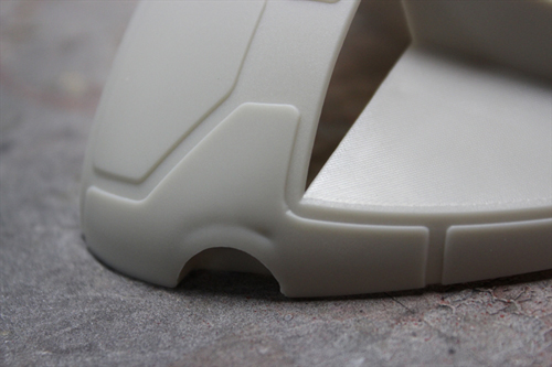
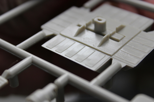
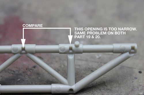
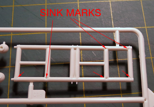
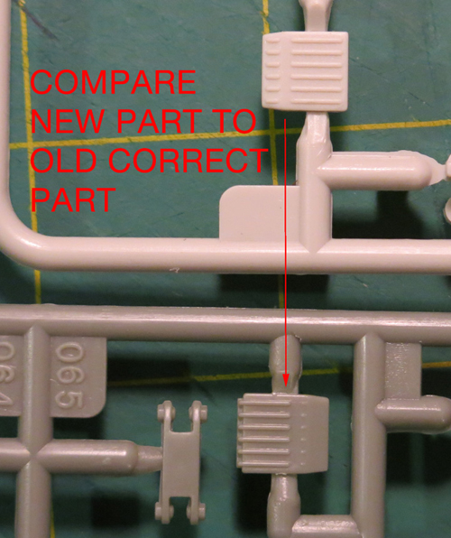
I guess I’ll start by saying that beyond flaws in the surfaces of parts caused by the tooling process that there was not a whole lot to be addressed. There were minor fit issues here and there with pins missing, sink marks etc. All were to be expected in a preliminary test shot. Other than that, the kit really assembled nicely once I wrapped my head around a few of the sub assemblies. It is one thing to see all of the parts and understand how the end product is supposed to look and see what assembly “theories” worked out and which didn’t. Even not noticing very slight differences between some of the frame tube parts caused problems in my first attempt. Keep in mind none of the parts get numbered until the next step. A few lessons were learned, but all for the better and the initial build went together satisfactorily.
I always ask for 10-12 initial test shots for plenty of testing and distribution to consultants and select media outlets. Most might think “ooh, 12 sets!” Well, they go pretty fast once you start handing them out. I kept three. One got assembled, one was used to retrace steps in the build to document trouble areas in the parts and one was kept intact for our archive. Three got sent to Jim Small to use for our buildup. That allowed extra parts for immediate replacement for the build and the ability to build a rescue pod in addition to the standard passenger pod. He was also due a copy as a consultant on the project. Our other consultants Daniel Prud’homme and Chris Trice were also sent one copy each. A set was sent to Sci-Fi Fantasy Modeller for upcoming issues. Two sets were sent to Mat Irvine to take along for his SFFM interview with Brian Johnson. One set was awarded to Jay Chladek for winning in the JerseyFest model competition. Let’s see… ten fingers and couple toes… Yep, that was all of them.
Back to the parts themselves, I mentioned we received a second round (only two sets this time) and most of the problems were resolved, but they never all get taken care of even at this stage. There were still about ten points to correct. The biggest problem to overcome was sink marks in the tops of the landing footpads. The parts were originally solid, but had to be broken into two parts each. This required a bit of rearranging other parts on that particular sprue to make room for the second sizable piece. The change resulted in more problems. In some cases, the factory’s work takes us a step backwards and this case was no different.
One of the features of the kit is that we are injecting it in two colors, “eagle” white and gray with windows supplied in clear plastic. This means that if one wants to, he can build the ship without having to paint it. I’m of the mind that is looks a little toy-like in this state, but adding the metal engine bell accessories helps, and just a little chalk dust added to the corners and crevasses would supply a superb look without painting in full. Here is a pic of Jim’s “naked” build with the larger metal bells installed.
Packaging- By the time test shots arrived, we were racing the clock to get everything finished. The instruction sheet needed to be revised to take practical assembly into account, decals had to be test fitted and refined, the test shot needed to be built into a respectable model for the packaging and publicity and I had the extra task of finishing the box lid illustrations. In most of the designs I was considering, I had a second Eagle in the background. I decided to paint that one separately and would later drop it in as needed in photoshop. This served two purposes. The angle I used for it lent itself better on the box ends. So I would need it larger than it appeared on the box face. Secondly, it allowed me a practice painting to exercise my languishing skills and to check my planned technique. If I couldn’t manage this “baby Eagle” as I like to call it, I was sure to fail at the much larger painting. I’ll post more on the illustrations and process on those another day, but I have to say I felt a bit wounded by some of the comments I saw out there when one of our distributors released a sales image of the box face. Everyone is entitled to their opinion and let’s face it you guys love this ship more than I do even in the very intimate role I’m playing in this. I know very few people could have known the hundreds of hours spent on the design, art and package. In the final push, I spent every waking hour for three straight days working on the larger painting. Time heals all wounds though and I feel much better now. Btw, usually when working on freelance gigs and even when I’m doing semi-mindless photoshop here at Round 2 I listen to podcasts more than music. One thing I used to pass and measure the time on this project was finding “books on tape” for free on youtube. My “reading list” was… 2001: A Space Odyssey (I get it now), Starship Troopers (I was struck by how closely the movie stayed to the book while still failing in its portrayal of the material), the first 1/3 to ½ of Stranger In A Strange Land unabridged edition (I didn’t really grok it so I moved on), 1984, A Brave New World and Treasure Island. I feel very well read now…

Other stuff- I was very hesitant to reveal all of the news I made in my last Eagle post because it all felt too good to be true and that any of the deals I mentioned could fall apart at any moment. And I’m sorry that I have to report that one of them did… for the moment. It seems the ability to move decals from Italy into China for pack-in is disastrously problematic without the proper red tape taken care of. This is something that is being worked through presently and we full expect to be able to use Cartograf decals in upcoming Polar Lights, MPC and AMT kits by mid 2016, but unfortunately it just can’t happen in time to include them in this release of the Eagle. We currently and will continue to include them in our Hawk and Lindberg branded kits. The move to change to Cartograf has sent a clear message to our current Chinese decal suppliers and stepped up attention to quality has been ensured. I have tested proofs of the Eagle decals and they performed admirably and responded to the use of setting solution. More updates on the inclusion of Cartograf decals will come when definitive info becomes available.
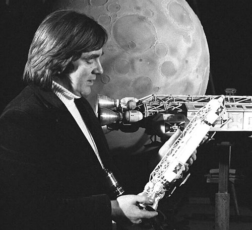
On the plus side, Mat Irvine’s interview with Brian Johnson seems to have gone off without a hitch. Since the interview Brian has delivered a special behind the scenes treat for Eagle connoisseurs, a rare photo of the Eagle model crew along with a full listing of everyone that worked on them!
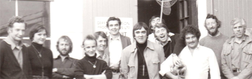
Pictured from left to right: Alan Barnard, Sallie Beechinor, Terry Reid, Guy Hudson, Brian Eke, Cyril Forster, Brian Johnson, Andrew Kelly, Terry Pearce, David Watkins, David Lichfield, Terry Schubert
Not pictured: Harry Oakes- DoP, Frank Drake- Cam Op, Les Bowie- Pinewood FX, Alan Bryce- Pinewood FX, Fiona Latto- Sec, Martin Bower- models
AGM Aeronautical General Models- Larry Barr & Wag Evans- 2nd 44” filming Eagle
Mary Robbins (Anderson), Nee Curtis- Sec 2nd Series 1999
Wrapping up- Okay, that’s about all comes to mind at the moment. Have a happy Thanksgiving!
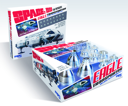
Oh… you ask when will the kit come out? It is November and that was the release date we’ve published, isn’t it? Yes, well, despite our best intentions November is not to be. Currently, it looks like kits should arrive in the nick of time before Christmas. No promises as always, but the honest truth is that is how it looks at the moment. I’ll post an update when I hear they are being loaded onto a boat. Until then… build a deluxe 12” Eagle Deluxe Edition or Moonbase Alpha. As always, Happy modeling!
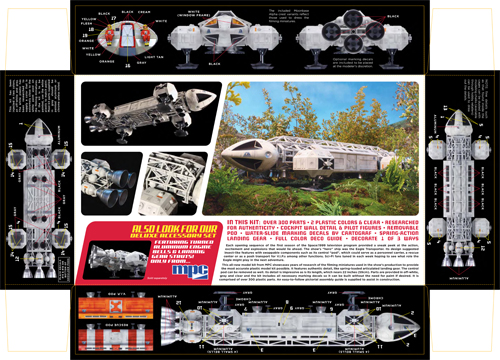
MPC Model kits: 22” Space:1999 Eagle update #5
Hi there Eagle fans. One last blog post to wrap up my series on the new MPC 22” Space:1999 Eagle kit. I might follow up later on with some process stuff about the box design and illustration, but I expect my next blog will be about the new parts for the U.S.S. Excelsior. But first, what more could be said about the Eagle…? Heh. Wait for it…
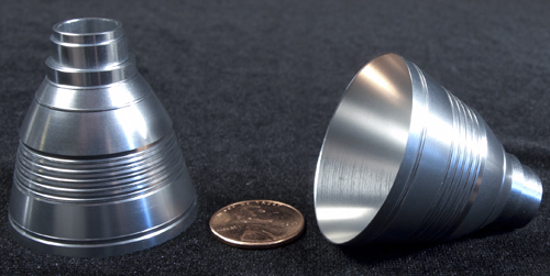
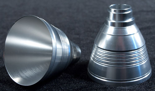
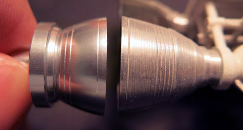
We announced at Wonderfest that we will be releasing a set of metal bells and oleo struts. Well, here is a peek at the first set of samples. They look great if I do say so myself. We need a small amount of adjustment on one of them, but otherwise looking good. The set of 12 aluminum bells and four oleo struts will retail for around $100.

Click to view the following image at full size.
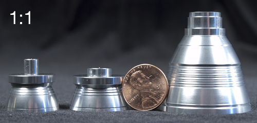
This shows the comparison of one of the VTOLs to an aftermarket main engine bell installed on a 1:96 scale Product Enterprise Eagle.
We recently decided to offer another smaller metal accessory for the kit, which will include the small shoulder pod RCS thrusters. These should retail for about $25-30. I’ll let you know when we get samples in.
Next, if you hadn’t heard we have on occasion had faulty decals found in our kits. In an effort to improve that situation we will be starting a relationship with the world-famous decal manufacturer, Cartograf out of Italy, and the Eagle kit will be one of the first to take advantage of their superior quality. Other kits will start using Cartograf decals as well with a couple trickling out towards the end of this year in our Lindberg products and more being used in our other brands early next year. Once we get some kits rolling out with them, we will evaluate whether to start using them across the board. Cartograf is THE name in water-slide decals having supplied decals for several other well-known model kit manufacturers. I recently tried a “side-by-side taste test” myself. I found that they “feel” thicker even though they are not, and they do not fall apart in water or tear nearly as easily. They seem to really suck themselves down to the surface of the model conforming superbly to compound surfaces. All kits that use them will have a sticker on the outside of the wrapping to clearly show that they are included. It is our genuine hope that this demonstrates how important it is for us to make sure our product is as high a quality as possible.

Last and hopefully not least, I think we have a bit of news that will literally put the kit over the moon. (okay, maybe not literally) We will have the ship’s designer and Academy Award Winner, Brian Johnson, review the kit himself in hopes of getting his endorsement to apply to the packaging.
Along with that I am thrilled to share even more excitement… Happy Medium Press, publishers of Sci-fi & Fantasy Modeller, are putting the final touches to the contents line-up for their Modelling The Eagle Special, due for publication early in 2016. They have given us an exclusive look at the cover, prior to them announcing the title on their site in the next couple of weeks. I’ve seen the list of potential article features and a great portion of it will cover more about our new 22” Eagle kit.
Well, what do you think…?
MPC Model kits: 22” Space:1999 Eagle update #1
A month has blown by and I couldn’t let another week go by without posting. I figured the hot topic may still be the new Space:1999 Eagle kit we announced at Wonderfest. Like I did back in June, I’ve written several posts that will appear weekly. We have closed the thread for the survey. Thanks for all of the input. We’ll be tabulating everything and I’m sure I’ll post some kind of response to the tallies later on. And now, on to the Eagle…
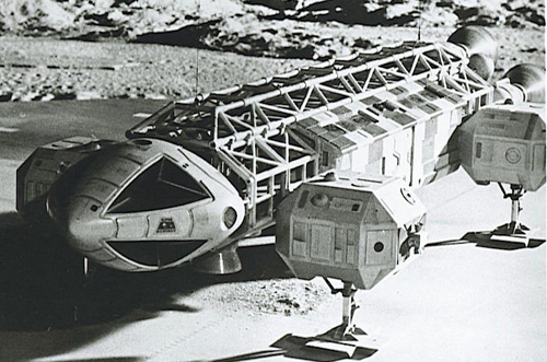
The kit is based on the ship as it appeared early in season 1. The model was redressed and details changed as filming went along. In some a few minor instances details have been simplified or compromised from how the miniature looked. The sub-assemblies of the kit will go together in much the same way as the original did.
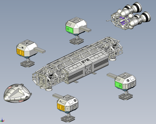
The kit will measure 21 5/8” long, which is exactly half the length of the 44” (it wasn’t quite that long) filming miniature that was used during filming of the show. The “true” length of the ship has always been a point of contention. Like the Galileo shuttle in Star Trek, it has the Tardis-effect of being bigger on the inside than it is on the outside. Most glaring is the fact that the doors on the personnel pod aren’t to scale with the doors martin Landau stepped through. The case can be made that the ship was longer. We landed on this length for two reasons. 1) 1/24 scale modeling materials were used to create both this miniature as well as the surrounding environments such as the MBA interior shots of the Eagle hangar. So, if you want to scratch build the environment to match the show, going exactly ½ scale from that is ideal. 2) From the development budget standpoint, the kit parts would have outgrown the amount of tooling we had estimated. Even just a couple inches longer threw everything off and driven up the price of the tooling to the point we could not have managed it. In the end, we figured the market would accept a kit in the area of 2’ long that was properly detailed even if the scale stated on the box was to be ignored. In order to sidestep the debate, I generally refer to it as the 22” Eagle and only state the scale for the benefit of the parties that require us to assign a scale.
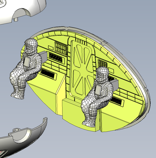
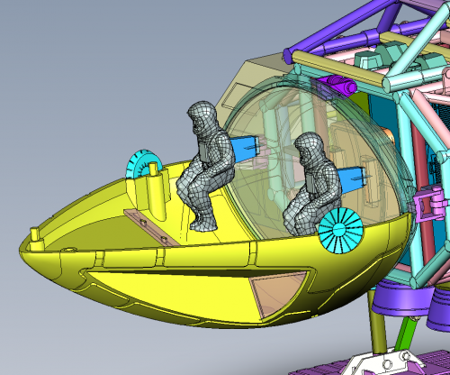
The kit will come injected in two colors, white and gray along with clear windows. The white plastic is a match to the paint used on the miniature. The kit will feature spring-action landing gear with articulated elbow joints. At the show we gave a look at the interior of the command module with it being a flat wall with figures mounted to it in much the same way as the original had. We have since found the opportunity to improve on this though and now that flat wall will feature relief detail that matches the interior set pretty well. A dash and console would barely be visible so those aren’t included. Again anyone that wants to add interior features like that as a scratch-building exercise will find the room to do that. Some have remarked that they thought the use of a screw to hold the pod in place will be a bit of an eyesore even though the original looked that way. For the sake of the stability of the model, we do have other attachment points designed in that would hold the pod in place without the screw. For the purists that want a completely removable/swappable pod these attachment points have been designed for easy removal.
Enjoy a few peeks inside the model. Next time I’ll talk more about the mockup.

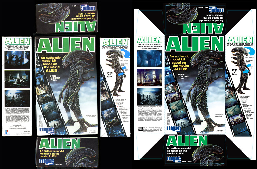
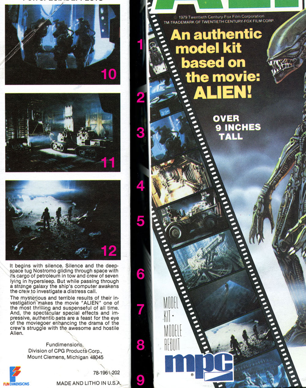
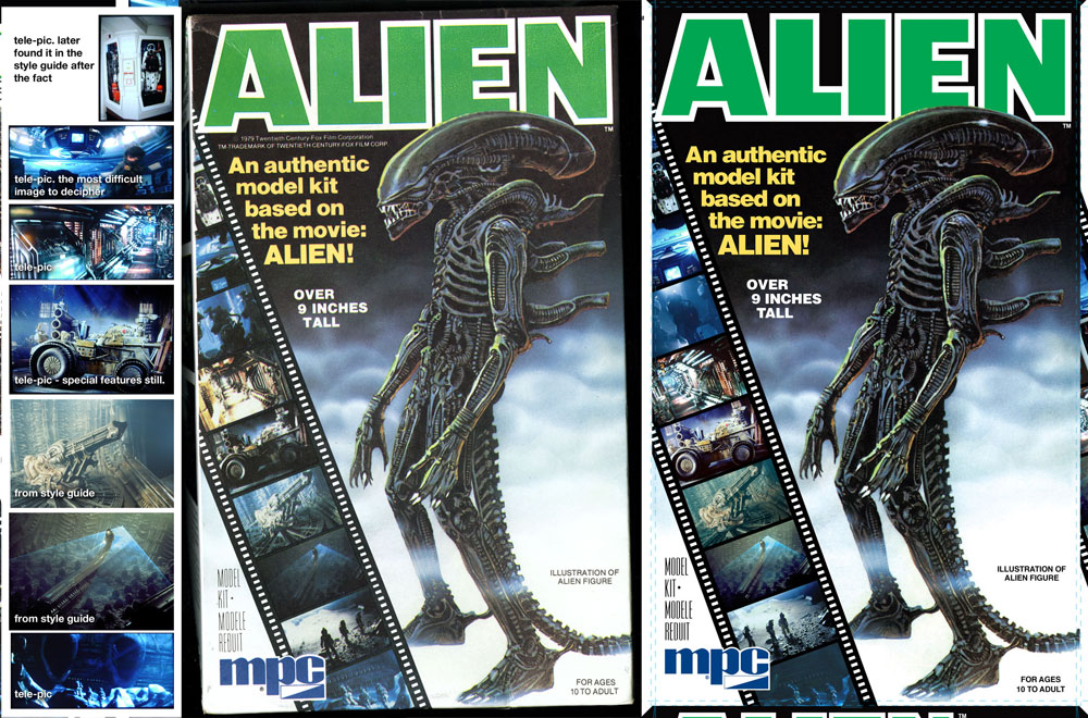
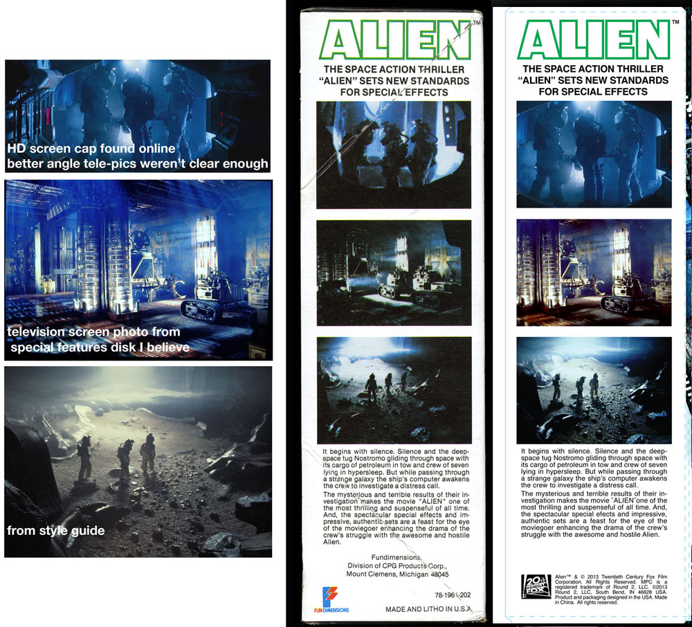
Round 2 Model kits: Recreating the MPC Alien Box Art
In the process or recreating the original MPC Alien box art, I had quite a time finding all of the images that were used originally. Modeler and historian, Mat Irvine, recently inquired about what the differences were. It was a fascinating hunt, so I figured I would reorganize my explanation and share it with you guys.
First, I’m showing the before and after images. The left side shows the original raw package scans of our vintage kit. The right shows our final production art. Whenever we reproduce a package we take a little bit of liberty to punch up the color slightly to account for fading. We replace any solid color with our best guess of the original CMYK values. In this case, the green in the word “ALIEN” was 100% cyan and %100 yellow. The scanner always captures values of magenta and black that was never on the original piece. Otherwise, we force black to become black, white to become white, etc. and generally touch up the image as needed to remove printing flaws or dirt.
The challenge of this particular piece was the small inset images in the filmstrip on the front and side of the box. I knew that many of the images were familiar and figured I could find them either in the licensor’s style guide assets or could be found online. Since they were relatively small, even medium-res images would work well enough. I decided to hunt them all down rather than spend time doctoring up the small shots that when looked at closely really broke up due to the larger dot size that was used during printing back in the day. Upon close review, the images were rather muddy.
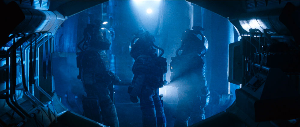
We’ve all seen the image of Kane walking the transom in the egg room and the shot of the Space Jockey. Images of the Nostromo corridor and pics of the trio in their EVA suits seemed familiar enough and seemingly didn’t pose a problem. I knew some shots were more obscure like those of the tractor on the front and the Nostromo storage bay on the side. I figured the rest would be discovered along the way with some deep digging. Little did I know what I was getting into. I’ll cover each one shot by shot starting with the easy ones…
#6 & 7 were the most straight forward as I found nice hi res pics in the style guide. And that’s where the “ease’ of the project would end.
#8 & 9 and maybe #10 seemed pretty familiar. I had to have seen them somewhere or another. As it turns out, “close” images could be found of #8 in the style guide. The positions of the figures weren’t quite a match, but upon reviewing the film, we never saw them in the film in that exact position either, because I watched it again… to find that shot and all of the others I was lacking. I defaulted to an HD screen grab found online to supply pic #10. I settled on using the style guide image for #8. I found myself resorting to more drastic measures for #9 and several others.
#5 & 11 I had never noticed in the film before. After watching again, I found them, but at different angles than what we see on the box.
#2 reminded me of the emergency helmets on the bridge of the Nostromo, but I’ll be darned if I could tell you where those suits show up on screen.
#4 was kind of tricky but #2 took the cake. The pic of the corridor is mirrored form what we see on screen. I eventually realized this and found a scene that was pretty darn close, but what the heck do we see in pic #2? Eventually, I realized the only way to figure that one out was to keep an eye out for anything resembling a perspective shot of something resembling a wagon wheel. I eventually figured it out. The image is a rotated shot of the ceiling in the bridge. I tracked down that shot eventually.
So how did I get the images I was missing? For DVDs we have an app for that, but the images are really small. Bluray is the way to go, HD with nice brilliant color, but we didn’t have a Bluray drive and pulling screengrabs from a Bluray is a complicated process. (which we eventually figured out after the fact) So, I basically paused the Bluray on my HD TV at home and took a photo of the screen. I had the lights out and camera on a tripod for stability. After some experimenting, I found decent enough results that they tightened up well enough for the packaging. In some cases, I tweaked the color balance a bit to more closely match the box. In the case of the tractor in pic #5, I found that buried in the image gallery (that I otherwise never would have gone through) on the special features disk. I found the suit in #1 there as well. I had a bit of egg on my face though when I later also found the suit pic in the style guide assets.
In some cases, there was no exact match and I settled for the best I could get. My theory is that since still photography from a handheld camera would have required a flash that we would have seen on screen. Therefore, my final hypothesis is that the shots on the box that don’t quite match were from cut footage of some kind. In the case of image #10, the characters are riding the elevator down, but in the film Kane is facing the opposite direction before the scene is cut. He never faces right with the elevator that low.
So there you go a great adventure in packaging design. Only the crazy few would dare go down this path. But, what the heck it was fun. In what other business do you have an excuse to watch a great sci-fi movie like ALIEN to make your paycheck?
GLUING A SNAP KIT IS A SNAP! …Part 3
Continued…
Puny Human Pin Hulk?
Whether you use the base that comes with the Hulk or you’re planning to use something different, I suggest you plan on pinning the big guy. Pinning isn’t difficult and will make your model more stable on its feet. It starts by filling the hollow foot assemblies with a solid material that will hold the mounting pins. I used epoxy putty that I pushed into the foot halves before I assembled them. The assembled feet could be filled with plaster of Paris just as well, but make sure all the water in the plaster has time to evaporate before you close up your model.
It hadn’t occurred to me to include pinning in this article when I was building my Hulk, so I will illustrate the procedure for pinning with another MPC snap-fit kit, the Vampire Glo-Head, Fig. 5. Round 2 has taken pains to make the model more stable than it was when originally issued, but I wanted to make sure it wouldn’t fall over at model contests. After the hand halves were joined, I filled the hollow interior with epoxy putty and sanded the bottom smooth.
Then I needed to locate the hole in the resin and wood bases on which I would mount the model. This hole also had to line up with the epoxy plug in the base of the hand so it would sit in the proper position on the resin base. While I held the hand in position, I penciled four alignment marks around it, extending the marks onto the resin base. Then I connected the marks with the aid of a straightedge, locating the centers of the holes, Fig. 6. They were drilled into the hand and base; for this model, I used a big screw for the pin, Fig. 7. A section of sprue or a dowel would work also. I used this technique to pin Spider-man to his base as well.
If you’re reading this article in the first place, I presume you probably weren’t going to leave your Hulk unpainted. His upper body and feet assemblies were designed to be trapped by the trouser halves. It’s easy to paint the trouser parts and Hulk assemblies separately and then join them together.
The fit of the Hulk’s upper body to the top of his trousers isn’t the greatest, and the seams along the trouser halves are prominent. However, they appear where seams on real trousers do, so they don’t have to be eliminated for a realistic appearance. The pieces of the test shot I assembled had to be glued and clamped carefully to prevent them from coming apart. The gap between the Hulk’s torso and his trousers can be filled fairly easily (I brushed several layers of white glue in there) and the paint on the trousers touched up.
A Model of a Different Color
Everything I’ve had to say about gluing the snap-fit Incredible Hulk applies to the Amazing Spider-man – and all other snap-fit models, for that matter. Spidey was designed so the red and blue parts of his costume could be snapped together unpainted. The design itself is ingenious, but it makes life harder for the modeler who wants to assemble the model with glue.
I tried and failed to remove the mounting tabs from the hands and feet assemblies, thinking I could paint them separately from the body and attach them after painting. It would have been much easier to simply assemble Spider-man entirely (which I eventually did) and then paint him. This required a lot of masking, but the results were well worth the effort.
The hardest part was to get the red and blue sections to fit smoothly. I sort of cherry picked the areas where one section would have prominence over the other. And the usual seams reared their ugly heads under a coat of primer, Fig.8. I had to be careful not to fill the incised web pattern when filling gaps. Where I did fill the webbing, I tried to resculpt it with hobby knives and even a fine routing bit in a rotary tool – that proved unnecessary as we’ll see.
Painting the web pattern may seem daunting, but I found a few ways to make it easier. Over a good base of white primer, I painted the red areas of Spidey’s costume with an airbrush, using Testors Model Master Guard Red. This is a very bright red and dries to a gloss finish. To paint the webbing, I mixed a bit of liquid detergent with some Hunt’s black ink in a small cup. The soap broke the surface tension of the water-based ink so it wouldn’t puddle on the gloss red paint. Using a fine, pointed sable brush made it fairly easy to apply the ink into the incised webbing.
I found it best to plan ahead when applying the ink so that I could avoid grabbing a wet spot while holding the model. I began painting the back of Spidey’s boots – these were areas where I could practice painting the webbing without my mistakes being too noticeable (rubbing alcohol cleaned stray ink marks off the gloss red paint). I tended to hold the figure around the waist, so the next areas I painted were the arms, then the head, and finally the torso.
The ink dried rapidly; to prevent my finger oils from marring it or the red paint, I wore rubber gloves while I worked. I saw that the intensely black ink looked the same in the molded webbing as it did on any parts of it I had inscribed. Even flat surfaces where the webbing got filled looked okay; on its own the ink reinstated the detail very well.
Time to Celebrate!
– Because I’m done with this article and a couple of fine models. I was very impressed with the final appearance of these snap-fit kits. Their engineering made me take some different approaches to those I’d have made with glue kits, but the results were otherwise the same. I hope you enjoy building your models as much as I did mine.