Recommended Sites


Posts Tagged ‘Star Trek’
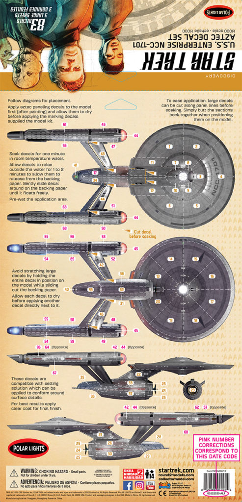
Polar Lights Model Kits: Discovery Enterprise decal numbering correction
How are you doing in this “new normal” hopefully you’ve been able to spend some time modeling as businesses reopen and we baby step our way through this ongoing crisis. Here at Round 2, our full staff has returned to the office after many weeks of working remotely from home. It seems like we haven’t skipped a beat. Well, maybe one beat was missed…
Because we have been working remotely, we couldn’t follow our usual methods of proofing and double checking and some errors were made in the numbering of our upcoming STAR TREK DISCOVERY U.S.S. Enterprise Aztec Decal Set. Some of you may know that the product was delayed slightly and missed being delivered with the kits and light sets. The numbering error was not the reason, but the delay in release did play a roll in the error. We will be sure all future production orders will be corrected. Without further ado, you can see the corrected numbers in this image and high res PDF can be downloaded here.
Polar Lights Model Kits: 1:350 scale Klingon K’t’inga update
UPDATE [11/8/2018] Klignon K’t’inga kits (and light sets) landed at our warehouse on Monday 11/5. It usually takes 1-2 weeks for kits to make it to retail once we receive them. So look for kits in just a matter of days!
Hi All. We just wanted to mention a few quick things about our all-new 1:350 scale Klingon K’t’inga model kit, and we won’t bury the lead. THE KIT IS ON THE WATER! That means it is currently on its way across the ocean to our warehouse. It should arrive there before the end of the month and reach retailers the first week of November. So, get your Halloween costume finished. By the time you finish your trick-or-treat candy, the kit will be here.
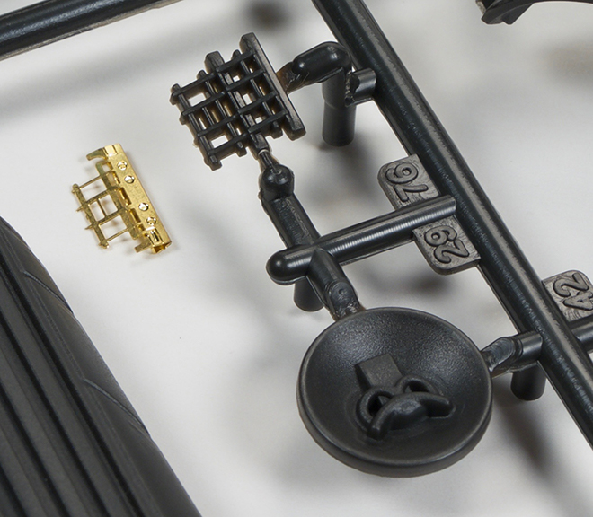
It has come to our attention that we haven’t really given much detail on one of the aspects of the K’t’inga’s Lighting Set. That is the photo-etch sheet that we have included in it. Many have asked what is included in that and why it would be needed. Well, there are several factors at play here.
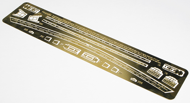
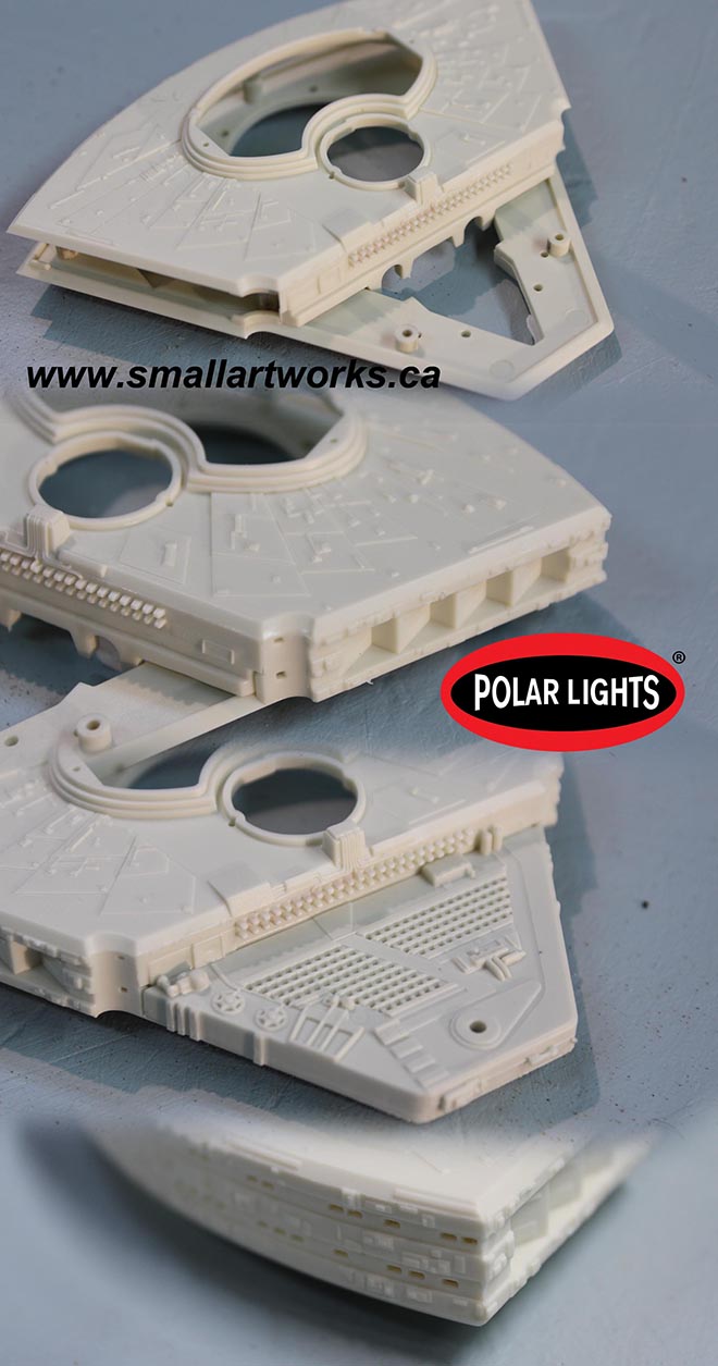
Some of the details on the studio model were too slight to properly replicate with injected styrene. We did the best we could with those parts in the kit, but the photoetch sheet allows us to offer parts closer to the original model. There were additional parts we wish we could have included, but they didn’t lend themselves to PE. In those cases, there is no better answer than to scratch build replacements. Modelers that are that particular will no doubt have the capacity to figure out how to do that.
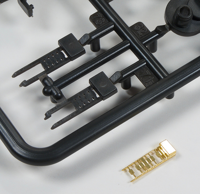
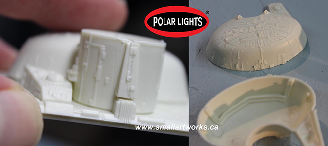
Two copies of this piece get stacked to create a more authentic replacement for part #76.
In a few cases, we didn’t have exact copies of kitbashed parts to copy when we started developing the kit. In those cases we worked form photographs and got as close as we could. Once copies of the real parts were found for reference, it was too late to change the part and stick to our release schedule. So the PE parts represent the real parts more closely.
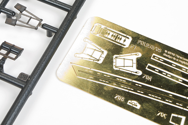
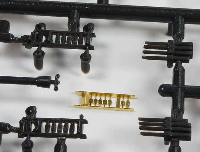
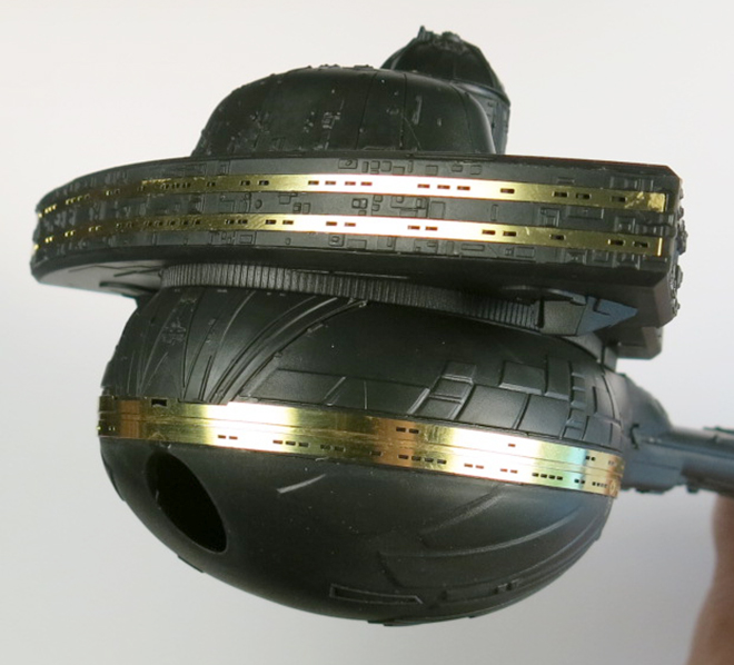
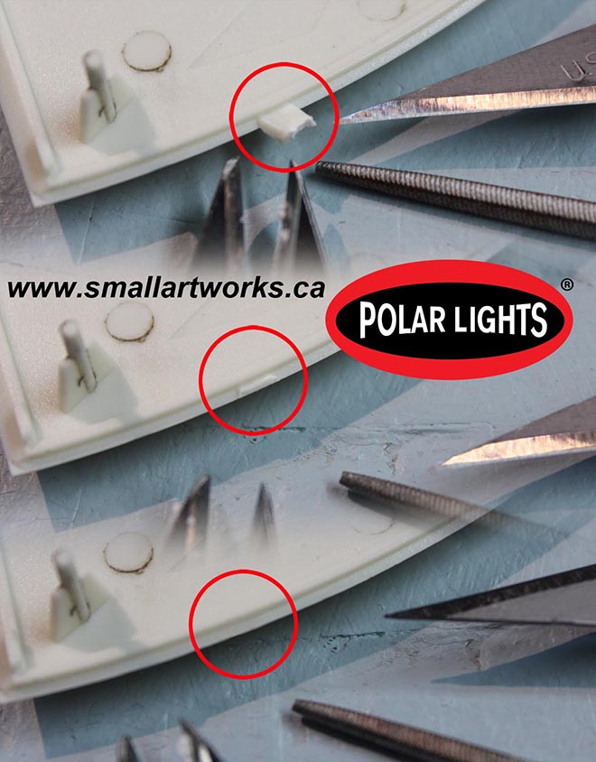
Another significant part of the sheet are window frames for the battle head. At 1:350 scale, (or 1/2 studio scale if you prefer) the windows on the cobra head and the bulb became very small. In fact, they are so small it is hard to inject them completely clean of flash. tool drafting also make them somewhat mis-formed in some places. We don’t mean to make it sound worse than they really are because the plastic parts aren’t terrible in this regard. They just aren’t as perfect as some will want. Now even the photoetch isn’t a perfect answer for the problem we wanted to address either because it WILL impact the accuracy of the model. The window frame strips are to be glued to the surface of the model which means they will protrude slightly unlike the studio model. So there isn’t a “perfect” answer, but we want to provide as many solutions as we can and let modelers decide which way they want to address it. Keep in mind that dealing with photoetch can be tricky for the uninitiated. It is intended to be used by experienced modelers.
lastly, we just want to mention that there is a an advance preview build going on that is hosted on the allscaletrek.com website.
You can find the threads for that here for the K’t’inga model kit.
and here for the Lighting Set.
They have also reviewed our recent release of the 1:1000 U.S.S. Grissom and Klingon Bird-of-Prey.
Polar Lights Models: Klingon K’t’inga buildup process Pt.7
Continuing our series of guest blogs covering our brand-new STAR TREK: The Motion Picture 1:350 Klingon K’t’inga model kit…
Finishing, The Final Frontier.
James Small, www.smallartworks.ca
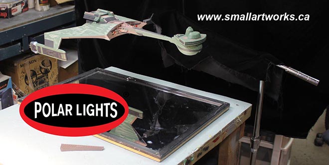
Not really much to tell on this post, the last of the series on building the K’Tinga from Polar Lights, Round 2. The pictures pretty much speak for themselves. After all the main colour coats were done, it was time to weather the model, doing so with a dark green wash to tie the colours together, some airbrushing with a tiny hint of black scorching and streaks of zinc chromate. Then the decals were applied. Normally one would say you should apply the decals BEFORE weathering but in this case the decals are small and I didn’t want them to be obscured, lest the low lighting conditions used for the photography would lose the markings altogether.
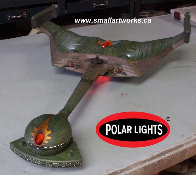
The decals were test prints sent to me by Jamie in slightly past the “nick of time” we would have liked, but they worked out really well. The only challenging decals to apply are the set of four that make up the big Klingon symbol on the bottom of the ship. When you do this as you finish your kit, make sure you take your time planning them out, and they will need a lot of coaxing and setting solution. The front “splash” surrounding the torpedo tube had not been printed at that time, so I had to spray that one on from scratch by first masking off the area, spraying on some gold and then following up with a touch of clear orange to match the colour seen on the Klingon symbols.
After all this was done, the model was finally finished and I began what would end up being one of the most challenging photo shoots I’d yet done for a model. It took me a full day to figure out the right balances of exposure, aperture for depth of field and lighting so it would all look wonderful on the box art. We also wanted to try to match the ominous look of the ship as seen in the film itself yet see all the details and retain proper colour balance. I had multiple light set-ups, bouncing light off the ceiling, walls, floor, some direct and some indirect, lights on stands, some attached to the ceiling, some on the floor across the room… it was a lot more complex than one might imagine for such a shoot and required a lot of time to figure out to get just the right look. Then I spent another day or two actually taking the shots. I took many dozens of shots testing it all before I could get it to look right. Because the model is so dark and required such long exposures at high resolution, microvibrations in the floor (even though concrete), in the air, whatever, maybe in the camera itself for all I know, made the camera move JUST enough to blur the image slightly. I also discovered that really long time exposures make a digital camera’s dead pixels (all digital cameras get them after even a short time of use, it’s a disease like tooth decay) really stand out like a klaxon! To account for the blurring, I had to do faster exposures with a wider aperture, and then stack shots so they could be stitched together by Jamie in Photoshop to cheat the depth of field. These challenges were exacerbated by the fact that I don’t really have professional photographic equipment, namely a more expensive camera (the Canon Rebel I have is a good camera but is after all, consumer grade) and a good solid tripod. Really good tripods that eliminate the slightest vibrations can cost a lot of money. Also, Jamie had very specific angles in mind for each shot, so it would follow his box art layout, and that took considerable time in some cases to set up and line up as well.
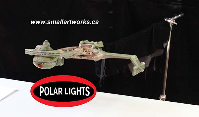
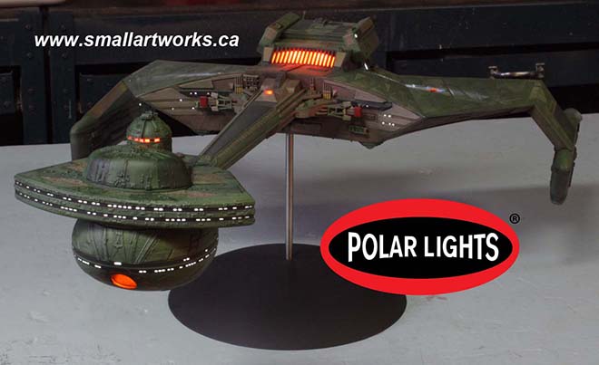
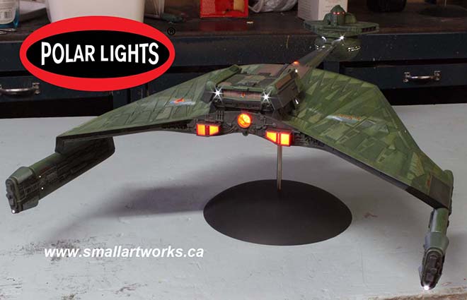
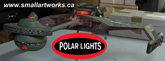
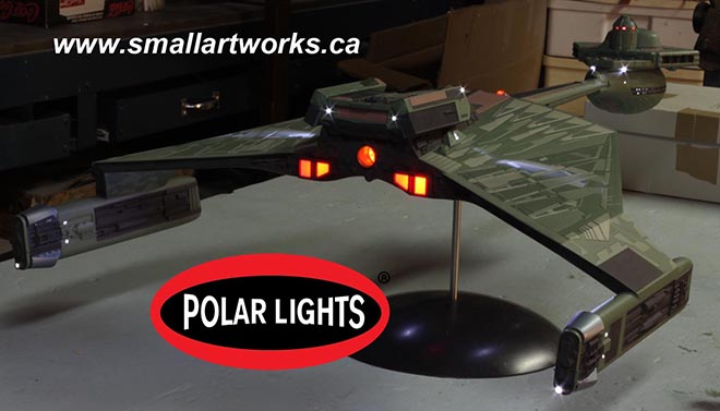
The build took far too long to do (I still have to paint the other two but I’m taking a short break from them to do something else for a while as I’m all K’Tinga’d out right now), the pix were done, the box art under way. I therefore present to you here and now the very first look (no, these are NOT the pictures used for the box art!) at the completed new 24” long K’Tinga kit which is right up there with the most comprehensive, most accurate sci-fi model kits on the market today!
We’ve tangled with solvents, paint and plastic. Now… it’s Chardonnay time. Cheers!
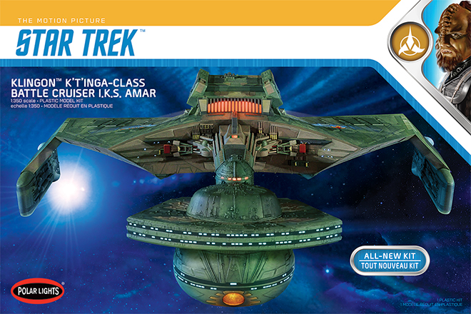
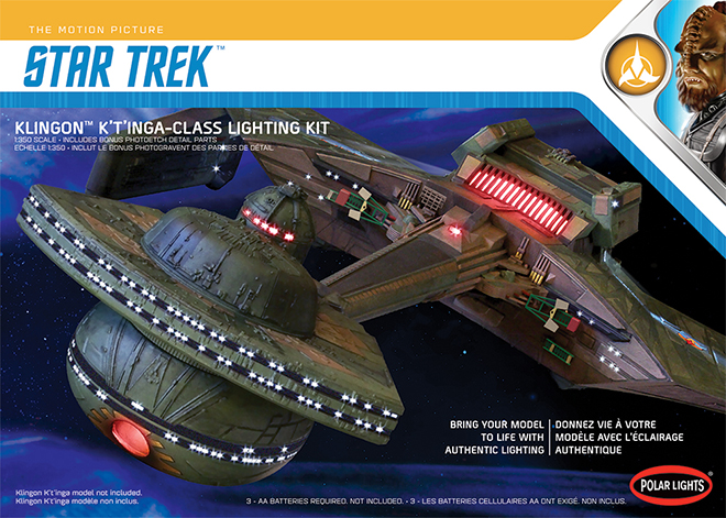
And as a special bonus, here is a look at the box faces for both the kit and the light kit!
Polar Lights Models: Klingon K’t’inga buildup process Pt.6
Continuing our series of guest blogs covering our brand-new STAR TREK: The Motion Picture 1:350 Klingon K’t’inga model kit…
Painting in Klingonese. The Grueling (But Still Fun) Part.
James Small, www.smallartworks.ca
“The Making of Jaws” pocket book printed back in the mid 1970’s has a funny line placed as a caption beneath one of the photos of the crew preparing to shoot a scene. The line has always stuck with me. I quote it a lot because I think it’s clever and is true of many things besides just film making. It reads, “It’s not the time it takes to take the takes, it’s the time it takes between the takes that take the time to take.” I was trying to find a way to adapt that to how you paint a model like this and fell short by a wide margin. The closest I could come up with is “It’s not the time it takes to paint the model, it’s the time it takes to prepare and mask the model that takes the time to paint.” Yeah. Really lame, I know. I’m not much of a meme generator. Hopefully I’m a much better model builder than a writer or I’ll have to go get a job at Wal-Mart.
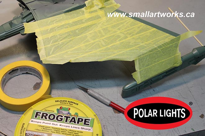
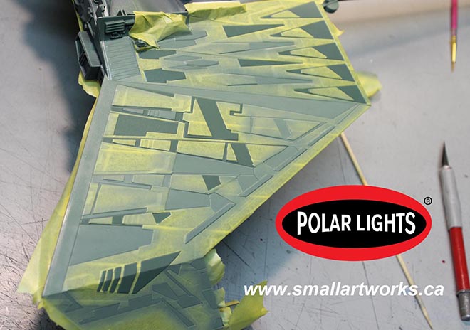
Anyway, the following shows what I consider by far to be the most grueling part of building this kit. It requires tremendous patience and even more masking tape. The tape itself is important. Make sure you don’t use some cheap-o no-name bargain tape. Use something that really works. I like to use “Frog Tape” which is readily available even here in the backwater town of Truro, Nova Scotia. It’s twice the price of standard painter’s tape but is better for preventing paint seepage under it than generic tape, but still a hell of a lot cheaper than the hobby tapes like Tamiya and so on, especially when you need to use a lot of it like on this model. It comes in two types. Regular (green) and the yellow stuff made for delicate surfaces. I used both as you will see. There are advantages and disadvantages to both. The green has a more aggressive adhesive, but the yellow type is semi-translucent and is less likely to peel off the paint you are masking over when you remove it. The hobby tapes are a lot thinner (meaning less wide) and people see that as a massive advantage. It’s easy to adapt the Frog Tape to do the same thing though. Simply lay a strip down onto a CLEAN, dry piece of glass and use a ruler and X-acto knife to cut strips to whatever width you like. Then just peel the tape off the glass when you’re ready to use it and put it in place.
But with the green paneling that covers the bottom and top surfaces of the main body and “wings” of the K’Tinga, I opted to simply cover the whole thing in tape and then use a pointed bamboo Kebab skewer, (but toothpicks could work too) to push the tape down into the nooks and crannies and then cut out the sections that will be sprayed onto. Just make sure the edges are pressed firmly into place. Because there are three different green colours, it gets a little complicated and confusing, and is really hard to describe here so I’ll let the pictures do most of the talking.
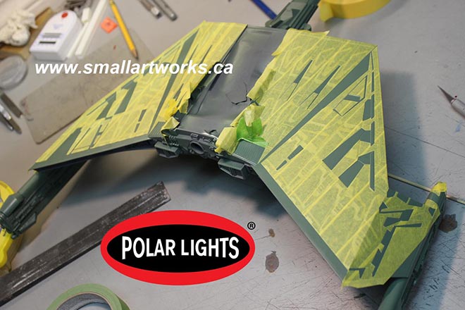
The yellow Frog Tape is laid down onto the darkest green painted surface. Normally you’d want to paint the lighter colours first and then cover that with the darker colours, but in this case the darker green is the main colour so it was put down first over the primed and light-blocked hull (the production kit will be molded in black so light blocking will not be much of a problem!).
The long and tedious task of cutting out the panels to be sprayed first, the “medium” green colour, begins.
Same for the bottom.
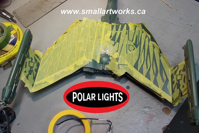
Spraying the medium colour with an airbrush is done and then the tape is cut out and removed for the next (lightest) colour of green to be applied. All the colours were mixed by decanting various rattle can paints into a mixing cup in previously determined proportions to match the colour chips that Jamie gave me to follow. How those colours were determined was covered extensively in Jamie’s previous blogs posted or linked to on this page.
With the medium colour done and dry, it’s covered up again and then the panels that will receive the lightest green colour are cut out and sprayed.

The green colours all applied, all the masking is removed. This procedure took me several days as the alkyd paint needed to be fully dry for 24 hrs or more before the next colour could be applied, and the masking alone took many hours. All the paint was applied with an airbrush, done by decanting the paint from the rattle cans into cups, mixed to match the colour chips Jamie provided me with and sprayed onto the primed surfaces.
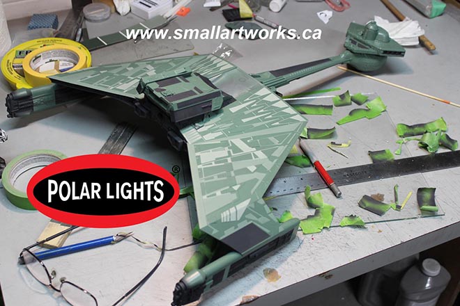
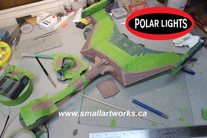
With the three layers of green out of the way, it was time to start laying down the other colours. This part was actually a lot more fun, as it was a lot easier, less time consuming and really started to flesh out the final look of the ship! This picture shows the model with the “light black” sprayed on. For this, I used 10 parts black Krylon primer (which is not true black to begin with but actually an extremely dark gray bordering on black.. difficult to describe!) mixed with 1 part white primer, and it seems to have the right effect. The nice thing about using primers is that it dries quickly, is less likely to react with the paints underneath and provides a nice silky matte finish.
The indescribable brown/tan/pink/oxide/mauve/taupe style colour… (I’m convinced that the VFX people said to themselves “Let’s see if someone forty years from now will be able to figure THAT one out when they try to build replicas of this ship!”) was painted on after the black, so all the green and black were masked off as one should expect and the pinkish stuff was sprayed on. Since there was also a lighter colour of pink to spray on, the same was done for it as was done for the green for various panels. I cheated in some areas and simply brush painted a few of them.
Starting to look the part, eh?
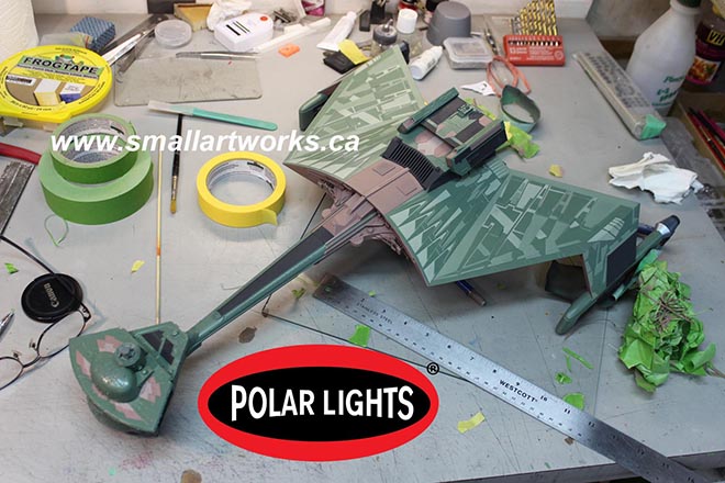
Now some of the smaller details are decorated using the old tried and true brush painting method using the small jars of easy to use hobby paints. There are some errors as seen here which will be touched up before proper photography.
The model is nearing completion. Lighting is tested and paint work evaluated. At this point I did some photography of the model in this state for some of the painting instructions that will be included with the kit. Jamie will work his Photoshop magic as required to perfect the shots as needed to make sure the model is accurately depicted.
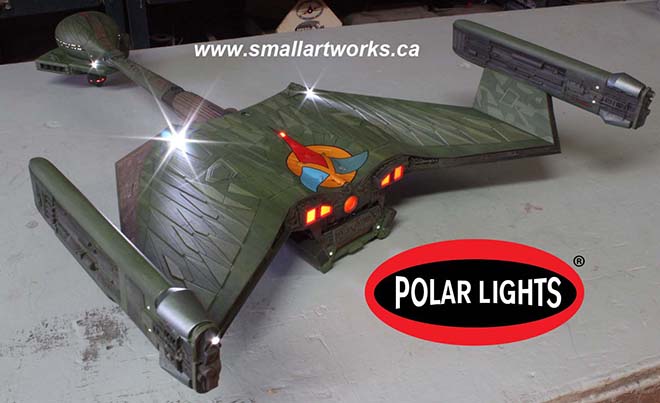
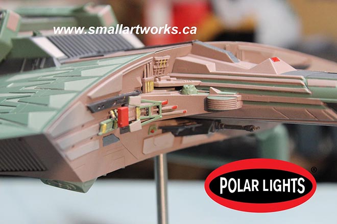
The mounting point modifications I made for this particular one can be seen here used as designed. In this case, the left grille, normally held in place with a magnet and seen here below the Polar Lights logo, is removed and the model mounted to a C-stand in front of a black velvet backdrop over a mirror to bounce light up onto the underside surface to give it a flat-lit appearance. It was shot using a 300mm lens from about 25 feet away, making the photos appear mostly orthographic so as to best show off the paint work in a blueprint-like format. The removable grille and other hatches designed into the modified kit as described previously allows the stand to be mounted into the model away from camera so as not to be in the way of any other parts of the it when photographed. This technique has become a staple for much of the photography I do for Round 2’s box art that Jamie uses to show how to decorate the kit for you, the builder. This makes finishing as clear as possible using actual photographs of the finished model in full colour instead of the usual crude grayscale diagrams that used to be done by kit makers in the past. Similar setups will be used after the model is completely finished with decals and weathering and dramatically lit for some VFX shots for the main box art photography.
Now you can see why I made all those modifications!
One more blog post to follow when the model is completely finished.
Jim did an excellent job matching the paint swatches I sent him, but everything turned out lighter in real life than I had guessed. I would never ask him to remask and repaint this ship. Luckily, we have the weathering stage to darken it up and the magic of Photoshop to get the look we want on the packaging. But did you see the light!?! Holy cow!!! -JH
Polar Lights Model Kits: K’t’inga… the colors, man… the colors… (Pt. 1)
Not to get confused with our buildup series from Jim Small, Jamie Hood has returned to share his research into the paint colors of the Klingon K’t’inga filming miniature featured in STAR TREK: The Motion Picture. Here is the first of three parts…
Who remembers this from a few years back…?
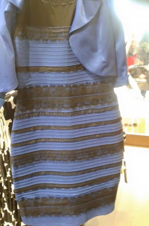
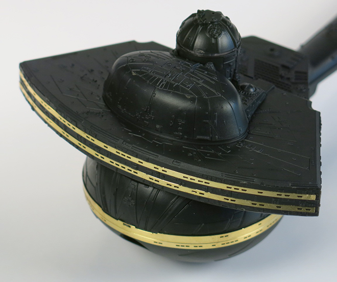
The world cracked in half trying to decipher the real color of this dress. Was it blue and black or white and gold…? (I guessed wrong, but who cares?) I have spent the better part of the last six months studying a similar conundrum in the paint guide for our upcoming 1:350 scale STAR TREK Klingon K’t’inga model kit. The goal is to supply a paint guide that would represent the look of the filming miniature on its first day on set. Why do we have to get that specific? Well, because changes were made to the miniature immediately before, during and after filming. Therefore, the way it looked the day it was first filmed is most likely the way it was intended to be. This story is a long and winding one, but I’ve learned too much not to share. Besides, I fear that without giving this complete explanation we will get letters about how we got it wrong. The truth is we can’t know exactly what it looked like that day AND no one says a modeler HAS to paint his model to match. You do you. Paint it however you want, but the decoration notes in the kit will be our best advice to this end. I’ve looked at this thing every which way, and though I am confident on the direction we will supply, I just changed my mind about some of these colors again yesterday. Besides determining the design of the small clump of detail that sits on top of the bridge dome, figuring out this color situation has been one of the biggest time sinks of this whole project for me. I’ve spent days (weeks) on both…
Let’s start with what we have to work with. Some of it you may be well aware of, some bits have just been revealed as our team has offered their best evidence for the paint colors that were actually used on the model. I’ll start with what we’ve been aware of for the longest time.
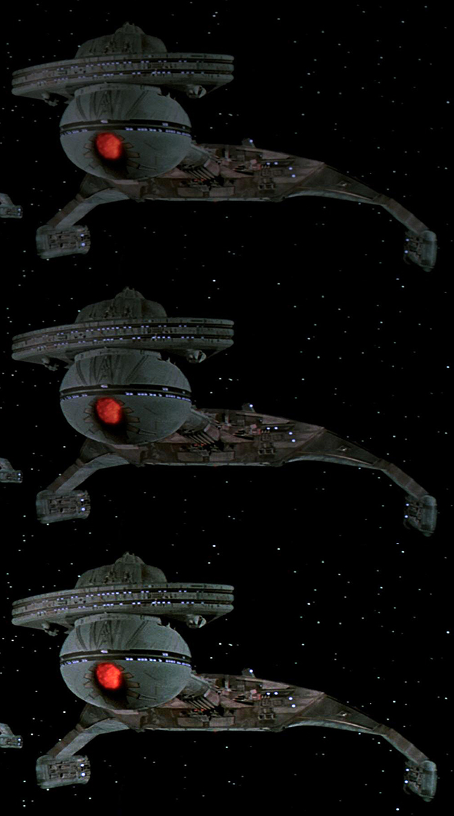
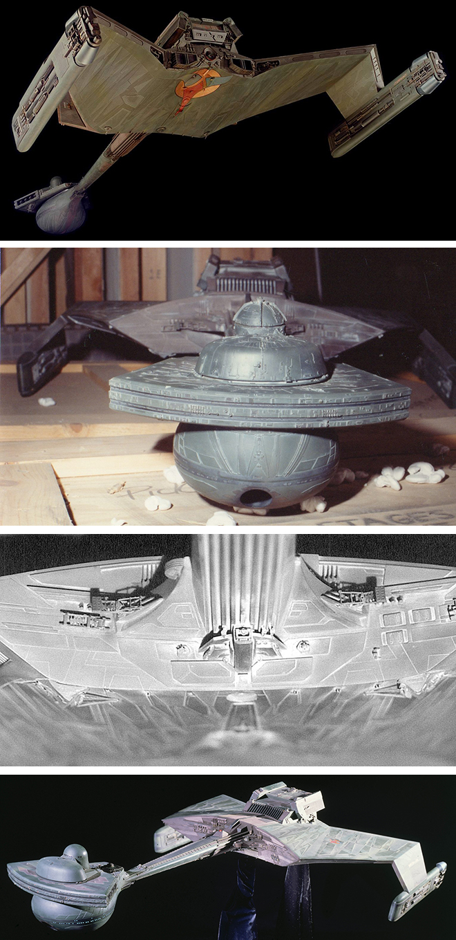
STAR TREK : The Motion Picture – The advent of HD makes it easier than ever to get a decent look at the ship in its appearances on screen although the color of the model was very washed out in some of its appearances. It isn’t the best we have, but it will become apparent how much it offers as I go. Photoshop helps too. It can punch up colors, adjust contrast and even sharpen images. It can actually pull hidden details out of shadows in some cases.
Cinefex 1 & 2 – These classic issues featured behind the scenes info on the effects process that shed a little light on how the model was handled.
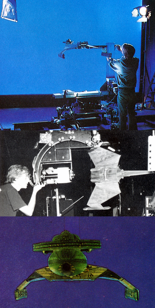
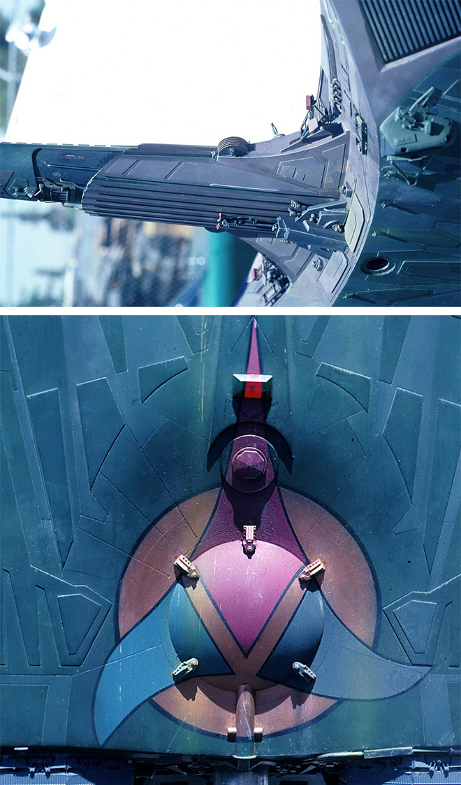
Bill George Photo Survey – A few years back FX production artist, Bill George, posted the series of photos he took of the miniature when it was uncrated for the ST6 redressing. I have had a chance to get further info directly from Bill as I’ve been studying the model. He did a great job IMO of photographing the model, but he stated they weren’t taken under the most ideal of situations. Shooting in tight quarters made the color wash out in some images. He said the color temperature of the images matches his recollection of the real model and this statement stood up when I took the step of checking the color balance in Adobe Photoshop. One mystery remains about the model as we see it in his photos though. You will notice a white substance that clings to the panel lines and other details on the model. Some might think it is dust that settled in from storage, but dust wouldn’t have settled just as much into the bottom of the model as it would to the top. This white substance is evenly distributed over the model. Bill said that it wasn’t powdery, but would come off when touched. The best theory we have about this was that it probably had to do with some of the “lightning” effects shown when the ships were destroyed by V’Ger. We have all stared at these great photos for so long, we are used to it and we see it as weathering. It really ties the whole ship together. But if it was used for special effects, was it there the first day of shooting? My working conclusion is “no”.
Michael Middleton Photo Survey – This set of pics was taken outdoors and in one case has an Apogee logo on them. (As I understand it, Magicam built the model and Apogee filmed it.) It is immediately apparent that the model was modified by Apogee after this survey, because details were added to the bridge dome including lights. The greater mystery was what more was modified after this set of photos was taken? Some of these pics have been floating around for a while, but they were low res and the color temperature seemed significantly different than the Bill George series. Trek Production Designer, John Eaves, recently shared high res versions of these images and more. However, they all had the same color temperature problem as the low res versions. These higher res images were released pretty late in the game relative to developing the kit. I wish we had them earlier, but they helped check our work and they also helped determine our color research once the color balance was corrected.
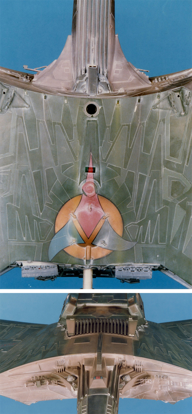
Various other photos of the miniature – These range from a lower rear shot that had been shared online by one of the guys that helped design the ship, Andy Probert. We also found an uncredited photo of the ship literally sitting on its crate after being taken out of storage. There is also a survey of black and white photos. They are relatively low res and they hold little value in determining color. I have been shown a few images that couldn’t be shared (Hey, this is sci-fi modeling… These things happen), but I think I can work around them and still make my point.
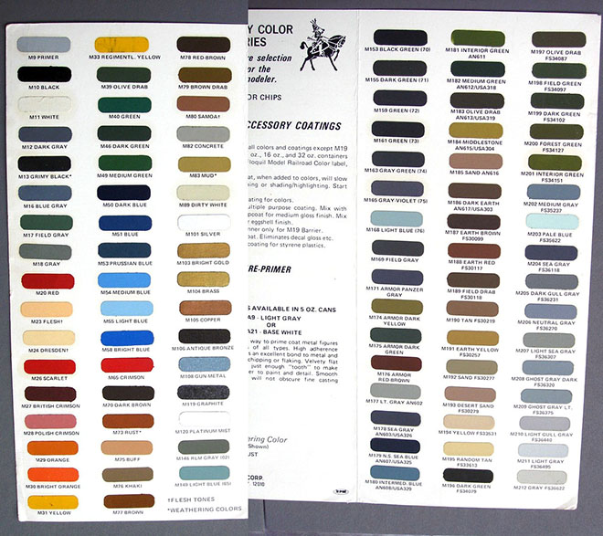
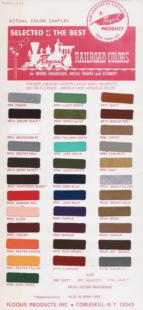
“Real” paint swatches – This is the latest and greatest! This was shared by Gene Kozicki who was working with Virgil Moreno’s estate. This is a scan Gene took from the original swatch card. Although it does not show every color used on the ship, it provides notes on a few specific model paints that were used. This lined up with additional information from Paul Newitt that Russ Simpson had brought his own full rack of Floquil paints to use on the miniature. In addition to this, Bill George received a couple paint matches from John Goodson who had run paint scans through the Smithsonian Institution’s database like they did on the ST:TOS U.S.S. Enterprise restoration. Although those results were a bit head-scratching, I think I know how and where they were used. More on these as we go.
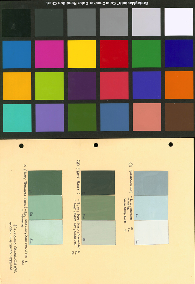
In the beginning of my study, I had to consider the possibility that the model may have been completely repainted at some point because the color in the oldest photos looked nothing like the color in the newest photos. But none of the reference photos we have were native digital files or even scans from slides or negatives, but scans of prints. In some cases, old-school photograph color integrity degrades. The original photos (or negatives even) could have color shifted significantly in some cases. So, was it repainted or was it just bad color balance in the reference? “Real” paint swatches helped, but they didn’t solve all the mysteries…
More to come…
Polar Lights Models: Klingon K’t’inga buildup process Pt.4
Continuing our series of guest blogs covering our brand-new STAR TREK: The Motion Picture 1:350 Klingon K’t’inga model kit…
K’tinga Build Part T’ree, Ready for Paint…
James Small, www.smallartworks.ca
This is the last step in the main building of the various sub-assemblies and main assemblies, rounding the bend now, getting ready for the really grueling part, the massive paint job. Not a lot to cover here but I do want to point out a few things, and it was my “overthinking” of a lot of it that put me so far behind. The biggest problem I thought I would encounter was the fact that the main body section of the ship has to be all sealed up after lighting is installed, so I wanted to make sure I didn’t make any mistakes before sealing up the top and bottom main sections. The way the kit is designed I thought would be … “unfriendly” at this point because I usually like to be able to install or at least be able to access a lot of the lighting gear even after main sections are glued together. For example, I wanted to be able to install the engines AFTER the main body was assembled so as to make clean up easier. That’s why on two of the kits I cut large sections out of the insides of the battery box tub so that wires could be reached with tweezers etc, to pull them back in if they slipped out and went back inside the body after I had it all assembled. This is STILL a good idea but it turns out my concerns were unfounded. I spent far too many hours thinking this through and it turned out to be unnecessary for the most part. However a lot of other time was spent thinking through the special requirements for the modified photo model too (which still took too long!).
Note: The rest of this mostly applies to the stock kit, not the one I made with the modifications for photography.
You assemble the engines with the lighting installed and the wires hanging out the top of the nacelles. Then you glue the finished engines to the bottom of the lower hull section pylons. You glue in the “wing radiators” at this time as well. With lighting firmly installed in place (AND TESTED!!!!) as shown, you can then glue on the top body section you see there, making sure to feed the wires in through the bottom hole in the battery tub. Once it’s all glued together, and if you are careful (remember that gluing hints article I referenced in a previous post) cleanup is really easy, no putty needed. With patience, it all goes together remarkably smoothly, everything lined up perfectly. Yes, it’s a bit of a chore to get all those locator pins to line up and all fall into place, but once you do, you just run a little liquid plastic cement along the seam allowing capillary action to do its thing. (I actually use a concoction of my own, a half-and-half mixture of lacquer thinner and acetone which is a lot cheaper and works better for me than the overpriced hobby glues and even dries quicker, but only works for joints where capillary action is used.) Press together, let the melted plastic ooze out between the joints and hold or clamp ‘til set. When dry, just use your knife to trim off the bead and you have a nice clean joint, no putty required.
Yes, I know the plastic is translucent. Light blocking will be done by first coating the model (after careful masking) with Krylon gray primer which is effectively opaque. The colour coats will be applied over that. Also, some lighting elements are not yet installed. Those can be done after all the paint work is done.
Next I glued the neck in place and held it to the body using elastic bands (modified model shown here but principle is the same for stock kit). Like joining the body together, just push it in place (everything lines up perfectly) then apply the thin glue along the edges and let it set. Once dry, I removed the elastics and was able to put on all the little greeblies that get attached to the bulkhead. I also installed the thin rear panels that go in between the wings at this time as well.
All three models’ sub-assemblies are finished (for the most part) and ready to begin the massive job of masking and painting. A few parts not shown here such as the top bridge dome will not be added until painting is finished.
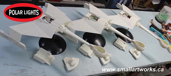
Due to time constraints to get the photography model done in time for Jamie to use for his box art and publicity material, I will now concentrate on just getting the modified model done first and will finish up the other two after the first one is all finished and photographed. Most of the time delay was my fault because I was overthinking so much of it.
Building this model is the easy part. Painting it will present some wonderful challenges… Hint: Most of the colours that were heavily researched by Jamie ended up being quite a bit different than I was expecting or appears to be in most photos! More on that as this build continues.
Polar Lights Models: Klingon K’t’inga buildup process Pt.3
Continuing our series of guest blogs covering our brand-new STAR TREK: The Motion Picture 1:350 Klingon K’t’inga model kit…
The K’tinga Build Part Deux, A Mounting Problem
James Small, www.smallartworks.ca
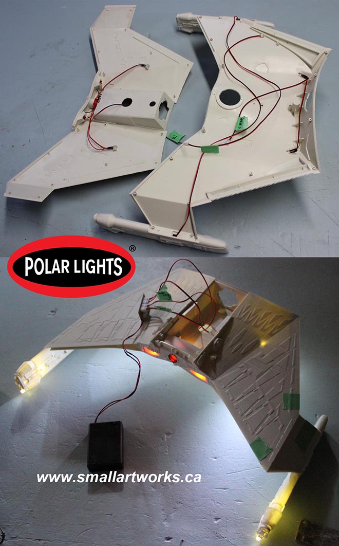
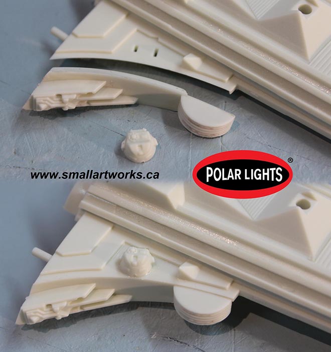
As I’m building three of these at once, I made the decision to modify one model to make it easier to photograph for the box art and publicity images. Therefore, this particular post deals primarily with the modifications I have done to this model to put stand mounts (AKA an armature) inside the model so that it can be positioned for photography at various angles, similar in principle to the way Motion Control miniatures were made for bluescreen filming back in the day.
The first thing was to decide where the mounts needed to be. One obvious mount is the stand hole that is included in the kit so it can be bottom mounted. That part is not needed to change of course, and Round 2 thoughtfully provided a plug/hatch that covers up this hole for underside shots and for people who may not want to use the provided stand. Another mount already built into the kit is also a natural, the torpedo tube on the rear. The inner tube is a bit short, and must still contain the lighting inside, but I can make a post to fit for the purposes I need. The way the kit is designed, this torpedo tube will be strong enough to support the model when mounted from the rear. However, I needed to make the model mountable from the sides and the top. Because of the ship’s design it’s impractical to make a mount for the front. For shots involving the rear of the ship facing camera, it can be mounted from the sides, top or bottom depending on the angle needed. It seems, based on photos of the original model on stage, that these were the mounts used on it as well.
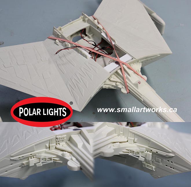
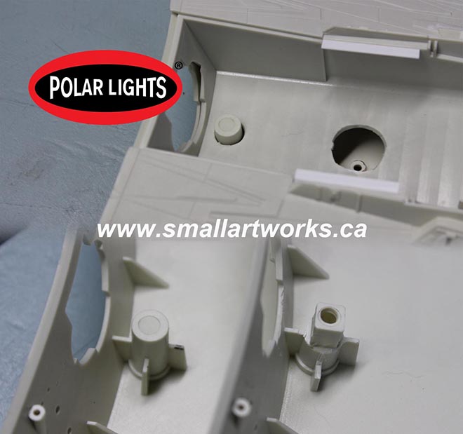
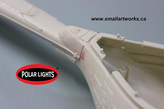
The stand hole molded into the lower hull section is deliberately quite deep and intrudes into the battery tub which is molded into the upper hull section (top), and I wanted to keep the upper hull removable until the model was at a near complete stage so lighting could still be installed. So I had to carve away some of the plastic so the square tubing I’d use for the armature would fit over it (bottom right) for support and without gluing. I drilled a hole in the top of that mount so that the hatch plug, which covers the stand hole when bottom shooting is required, could be pushed out from the backside when its removal is needed.
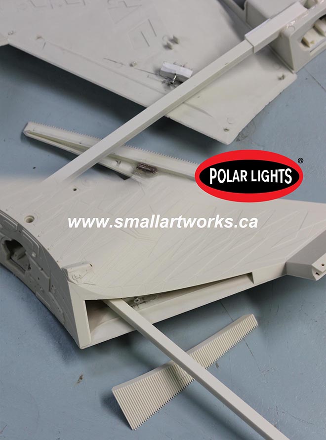
The armature, entirely glued into the upper hull battery tub section was made from Evergreen styrene square tube to fit the stand mount square stock (rather than cylindrical tube) so that the model would not have a tendency to rotate during set-up for shooting. Visual effects miniatures usually use much more robust armatures machined from aluminum or similar because the fairly large and heavy models must be kept rock steady during motion control filming, but this kit is so light that plastic armatures are good enough for my still-shot photographic purposes. You can’t really see them in the photos here but extra web reinforcement was also glued to the back of the square tube mating with the battery tub for added strength. Sections of the tub were also cut away to aid in wiring for the lighting as well as access to other sections during construction and/or possible servicing. The side armature had to be kept short so that it would not block the lighting for the forward bulkhead up front. The light will be blocked when the stand mount is plugged in but that won’t matter since I won’t use the side mounts when that section of the ship shows to camera. The top corrugated panel on the forward section of the main body was made separate in the kit, which is perfect to aid in painting and also act as a natural hatch for the top mounting point. A pair of glued on neodymium magnets hold it perfectly in place.
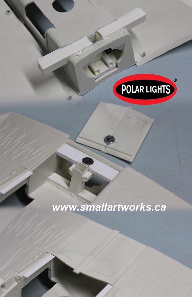
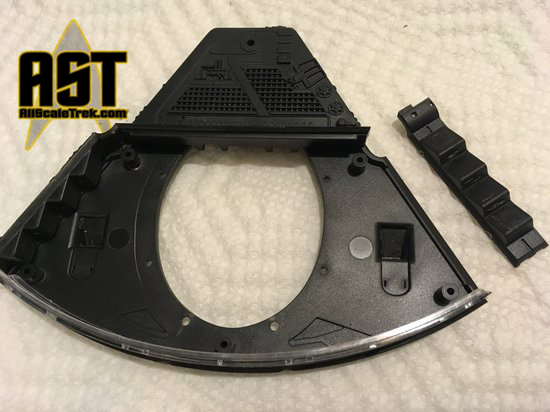
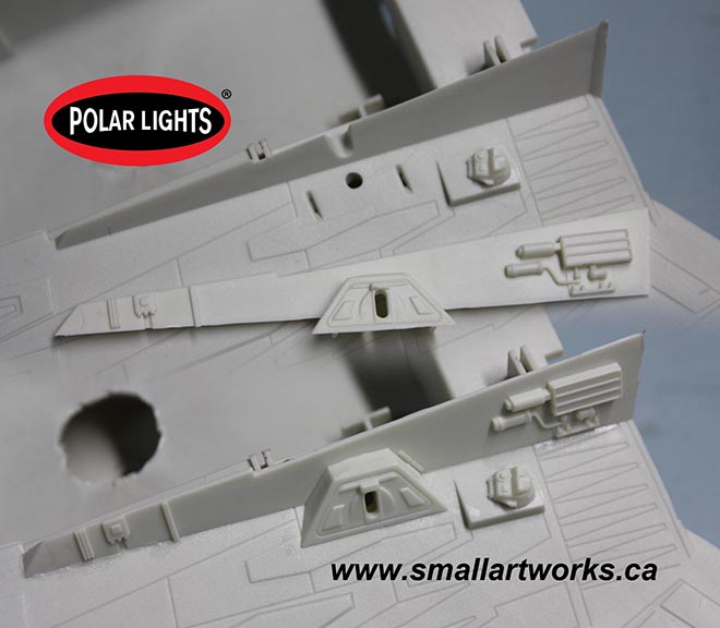
The problem with the side mounts is that, even though the grilles on the sides look big, they are at a very steep angle (about 60 degrees) so the side profile makes them very narrow. This had to be taken into account when planning the mounting rods and armature. But the problem was that the grilles on the kit were made to be cemented in from the backsides of the body before you attach the top. How to make the panels removable, yet easily replaceable when the model is finished? The answer can be seen here. First, the grille panels were modified so that they could be placed from the outside. Then a magnet was added to the inner surface. Why is there a screw? Because when you’re dealing with this kind of thing with all those crazy angles and no apparent mounting surface, you can’t be absolutely sure where things are going to fall. By putting a screw (which the hatch magnet will stick to) into a solid point deliberately set further back than you might anticipate, adjustments can be made if things don’t line up quite right.
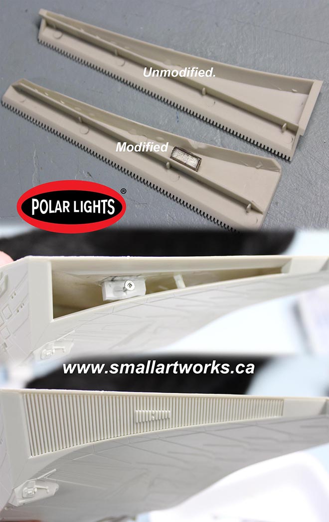
Here you can see the grille hatch unmodified and modified with trapping sections cut away and a magnet added. Then you can see the result of what the finished model will look like with the grille hatch removed and attached. They work fairly well. How do you remove the hatches? Because the screw is roughly in the centre of the hatch and acts as a crude fulcrum, you just push on one end, the other end pops proud and you can just grab it to pull it free. Another advantage in making those grilles removable is that I can complete some of the wiring even after the top and bottom body sections have been glued together. I still have the likely problem of light leaks around the removable grilles. I’ll work on that next along with a bunch of other things. More stuff to think through.
Looks easy doesn’t it? But with many things, it takes a lot of thinking to come up with the simple solutions to what look like complex problems. There are so many crazy angles to think of here that it seems very daunting at first, and you have to think ahead and carefully examine everything. Will it impede lighting? Will it stop the assembly from going together right? Will it allow for stand clearance? It takes time to work all that stuff out and you don’t want to make a modification that won’t work and become impossible to reverse. In fact I’d say ~90% of my time in building this model’s various modifications so far was spent thinking about how to do it and if there were better alternatives. In some cases maybe there are and I just didn’t think of them. The actual work itself takes relatively little time once you come up with the idea.
Meanwhile, if you future K’Tinga builders out there have a desire to mount your model from different points other than the standard bottom mount, maybe what I’ve done here can give you some ideas of your own.
Enjoy!
Polar Lights Models: Klingon K’t’inga buildup process Pt.2
Continuing our series of guest blogs covering our brand-new STAR TREK: The Motion Picture 1:350 Klingon K’t’inga model kit…
The Ktinga Building, Part One
James Small, www.smallartworks.ca
Oh, OK, I won’t bother with the double entendres and food jokes with this one. Just the straight up dope this time, albeit not with a lot of pictures. Most of my time was spent just looking through the parts, test fitting and comparing them to the CG model (used for the tooling) and gaining an understanding of what goes where and when certain parts should be assembled and which ones should be left off until lighting and painting can be done. That’s the way it goes when you’re building a kit (actually three of them in this case) for the first time without the instructions that will be included in the final kit! I’m also doing what I can to document it for both this blog and for possible ways to make minor improvements in the kit as we go along so such changes can be incorporated into the kit as you people will be buying it. The test shots have been done, but small improvements will still be made, which is why they are called TEST shots. Also, I wanted to actually get PAST the points covered in this blog to make sure I covered it all needed before the next. Lotsa back-and-forth with this one.
First, I will let you know that I will be describing this build with the lighting kit being installed, as this is the most comprehensive way to do it. If you will NOT be installing the lighting (why would you NOT want to light it up???) then you can take obvious shortcuts, but I will not deal with those shortcuts here.
I wanted to assemble as much of the sub assemblies as I could before the lighting or painting needed to be applied. That part turned out to be a bit tricky as this is one of those models you need to do a little bit of each as you go along. That means there will be assemblies you will build, then you will install SOME lighting, then you will build some more, do a little painting, then put in more lighting, then more building, and back and forth and so on until it is finished.
The next thing I want to talk about is how to properly remove the parts from the runners. There are a lot of delicate corners and edges on this one, but if you are careful removing the runner gates, no putty will be needed to smooth things out or hide joints. The pic FIG 1 shows the procedure. First, cut the part from the runner while still leaving a good chunk of the gate attached to the part. Then, using your nippers or a sharp blade, slowly whittle off the remaining nub. Finish the surface off using a needle file. The better you do this on EVERY PART of the model, the better the parts will fit.
The first parts I assembled were the “Cobra Heads” of all three models. When the above parts preparation procedure is followed and you take your sweet time assembling, the parts fit together absolutely perfectly with no puttying needed and almost no cleanup except for a slight scraping of the edges with a sharp knife after the glue has set. The procedure used to properly glue these parts was covered in an article I did years ago for Round 2’s now defunct “Workbench” page, but can be viewed here on the Small Art Works hosted CNSM page for those of you who would like a refresher.
http://www.smallartworks.ca/CNSM/VS%20build/Pretty%20In%20Mauve.html
Note in FIG 2 that no putty was needed to successfully assemble the parts which are well engineered. I’ll let you in on a little secret here. Although some modelers demand such amenities (which is why Round 2 provides them), I deliberately did NOT use the clear window parts supplied with the kit that would normally be installed behind the outer hull window panels. I find that too difficult to work with (though some modelers have no problems with it). I instead will leave the windows unglazed, then after painting I’ll fill the window holes with Testors “Clear Parts Cement and Window Maker”. Microscale makes a similar product called “Micro Crystal Clear”. In a p[inch white glue would even work but white glue is not as transparent. Then, when the model is finished, a clear dullcoat spray will fog the windows enough to provide properly diffused lighting from the LED’s inside.
Because it called out to me, I quickly assembled the bridge cylinder and the elliptical section that sits on top of the cobra head because those were so easy to do. The elliptical section glues together so well that the gap is unnoticeable as it falls on a natural panel line. Then I glued the cylinder to the cobra head section and noticed a GAP! OH NO! Naw, false alarm. The gaps that you see in the pictures are actually supposed to be there. It’s likely a result of the original VFX miniature being made that way, because the bridge section was made removable for maintenance and so, yes, those gaps are authentic! So before everyone complains, that is NOT an error of the kit! See FIG 3. Very little clean up was needed between the two cylinder halves.
The next thing I assembled was the lower part of the head which I call the “bulb”… because… duh… that’s what it looks like. The best way to go about this (hey, I had three tries, eh?) is to cement the forward part of the top half of the bulb together with the two sides of it so that all three parts of the top half of the bulb are properly aligned. Do this while continually testing (but not gluing it) to the cobra head section that will eventually be permanently mated with it. Then, when the glue has set, cement the top to the bottom half and then glue the window sections in place as shown in FIG 4. The torpedo tube was also glued in at this time as well. Any slight overlap of the window section relative to the bulb section can be easily trimmed down or disguised by the fact that the entire window section will be painted black, so the parts seam line will be naturally disguised by that very obvious colour difference. This deficiency is being worked on by the factory to improve the fit. Also, a decal for the darks tripes that go over the windows will be provided. The bulb is NOT glued to the cobra head yet. That will be done after the model is painted and the lighting is installed.
Next I glued on some rather insignificant detail parts (FIGS 5 & 6) because there were bits that would need to blend into the finished model which did not need any special treatment and could be added without being detrimental to the lighting system that would later be installed or impede paint work.
The sharp eyed observer will notice the direct tie in to Star Wars on this model. Yes, the foot pad from the R2 D2 MPC model kit was actually used on the original filming miniature exactly as you see, tying Star Trek and Star wars together the way only ingenious model makers can! In this case, R2’s foot was used as the vehicle from which the Klingon insignia spotlight would shine. See FIG 6.
I did find just one spot that needed some putty between the joints, but it’s a very easy fix. See FIG 7
Quite a bit more has been done to the model since these photos were taken which will be covered in the next installment.
Polar Lights Models: Klingon K’t’inga buildup process Pt. 1
Just like Santa takes a vacation the day after Christmas, model kit brand manager Jamie Hood has dropped off the goods (in this case, that means K’t’inga test shots) and is off on vacation. In the meantime, Round 2 consultant and model builder Jim Small will be sharing the process of building our display model that will be featured on our box art and will be making appearances at shows like Wonderfest next year. We hope you are hungry for this series of blogs.
Three Delicious Servings of Styrene Goodness!
James Small, www.smallartworks.ca
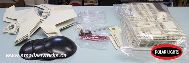
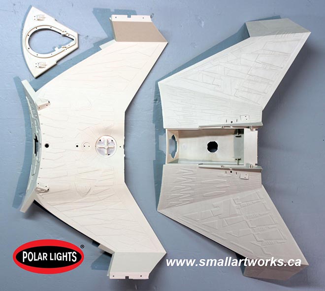
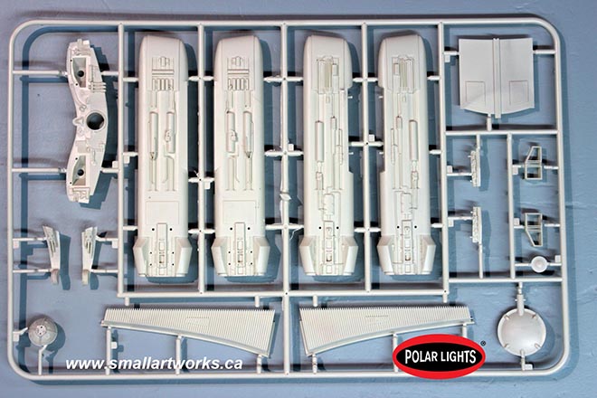
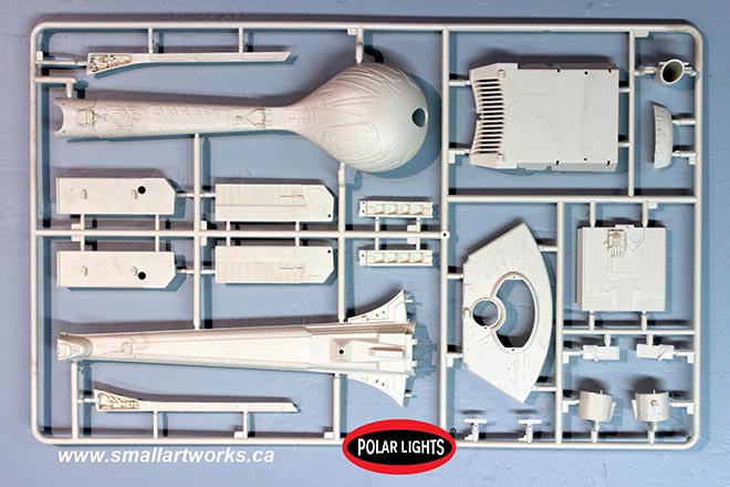
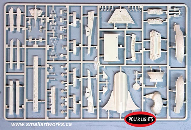
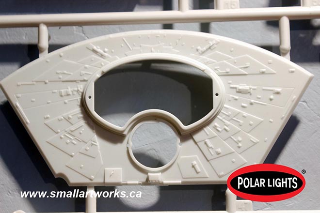
Well, well, well!!!! Look at THIS!!! A wonderful plate of appetizers came to the carnivorous lair of Small Art Works today, filled to the top with three test shots of the next fantastic model kit release from Round 2 and Polar Lights! I’ll be building all three of these at once, assembly-line style for the most part. All will be lit, but one of them I plan to try and install mounting points on the sides, top bottom and rear of the ship the way the studio model was done, which will aid in the photography I’ll need to do for publicity photos and box art etc. Only one lighting kit was supplied by the factory so I’ll have to scratch the lighting for the other two. Several parts had come loose from the runners and were put into ziplock bags. Each of the three main large sprues shown measure over 17” x 11” in character, so that gives you a good idea of how big this model will be!
I’ve taken some pictures of all the sprues here so you can see for yourself the delectable ingredients supplied with the upcoming kit, the loose ones were put in place into the runner locations they came from to show you. The parts are very crisp and clean, panel lines are perfectly recessed to match the original and the fine seasoning of detail is very sharp! This kit is exactly half the size of the actual filming miniature as seen in Star Trek, the Motion Picture. Yes, this kit really IS as good as it looks to be and will make a satisfying full course meal for all avid Trek fans!
As I write this I have examined the parts overall and have tested the lighting system. Next I will be studying it all to figure out the best way to cook this thing and work out assembly and painting strategies. Likely I will be looking for the “quick” subassemblies to get out of the way first.
The biggest challenge of this kit will be the tasty paint work… the “icing on the cake” as it were, as there are many colours in this menu which will need a LOT of masking! Jamie will be supplying me with the paint colour information as he’s probably THE world authority on this model by now because he’s been preparing for this feast for quite a few years and has worked tirelessly to make it as complete and accurate as possible! He knows more about what goes into this dish than just about any other galaxy class chef at this point.
I’m going to really enjoy preparing these meals over the next while, and I’ll post my progress here as I go, so bookmark “collectormodel.com” and keep checking back! You may find some of what I bake here a helpful series of hints to supplement the main recipe that will satisfy your taste buds when you place your order!
Let’s get ready to dine with the Klingons! (Bring extra napkins, and yeah, I was hungry when I wrote all this.)
EjIMBo
![]()
See how crisp and clean the fine detailing is? Delicious!
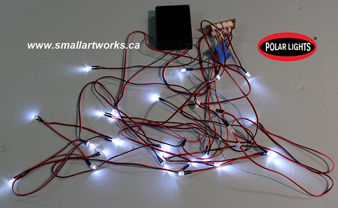
Quick-and-dirty testing the lighting system. Looks like a mess here but it’ll be worked out. Two of the bulbs flash which is why one is off as it blinked during exposure. All lights work perfectly.
Higher resolution pics can be found at the Small Art Works Facebook page here.
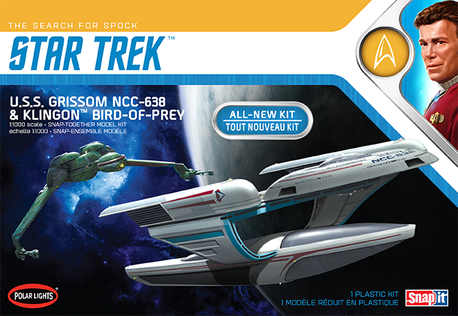
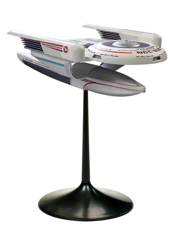
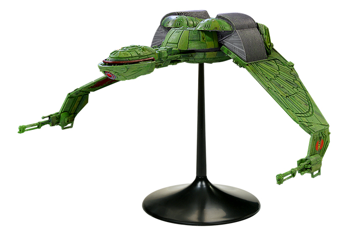
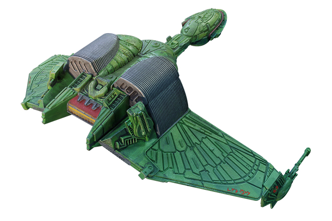
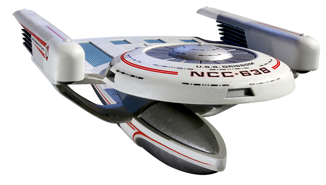
Star Trek Models: Klingon Bird-of-Prey & U.S.S. Grissom
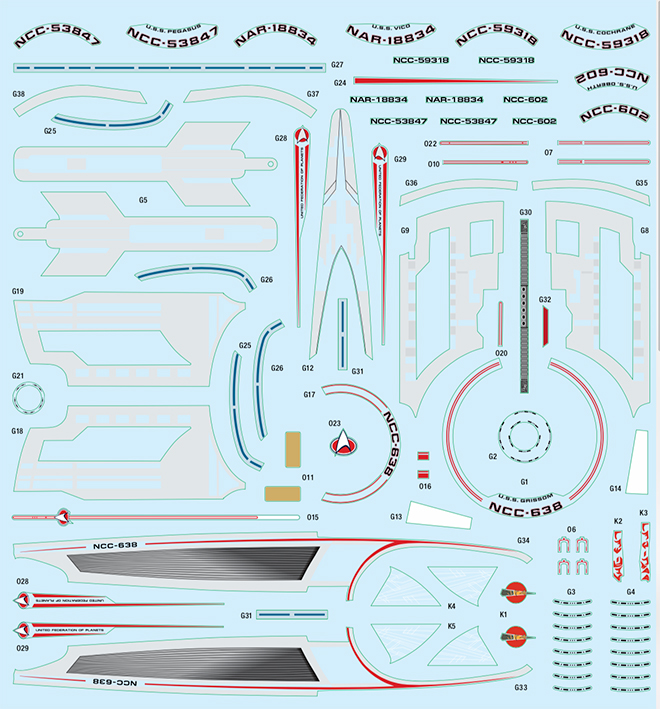
[UPDATED to show decal sheet]
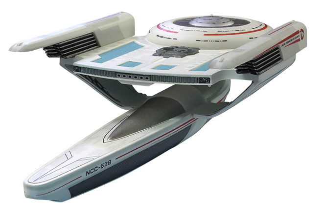
In the midst of summer activities and staying at work on our new Klingon K’t’inga kit, we don’t want to overlook another exciting Polar Lights kit we have in the works – the Klingon Bird-of-Prey and U.S.S. Grissom 1/1000 scale snap-together kit. These are two fan-favorite ships and the Grissom is getting produced as a kit for the first time ever thanks to the numerous requests we’ve heard over the years. These two kits make a fine addition to our line or 1:1000 scale snap kits.
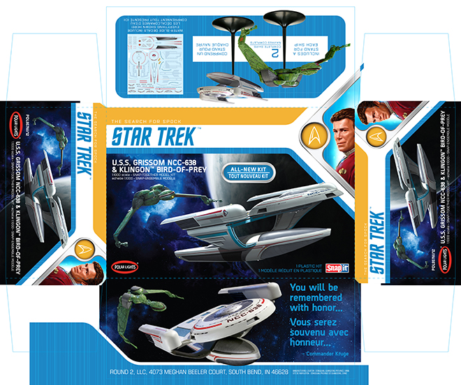
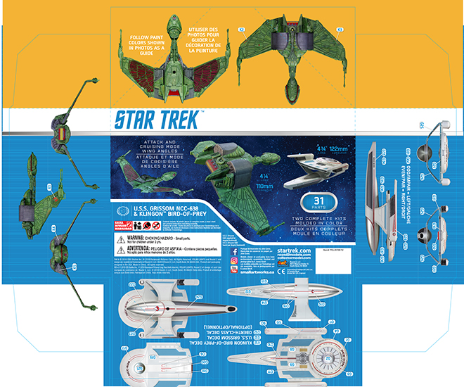
Here is a look at the packaging which features box lid artwork by Star Trek Production Artist, John Eaves. The box utilizes the updated Star Trek style guide and as has become our habit, we show a full color decoration guide on the sides of the box bottom. Both models come with stands and the Bird-of-Prey can be assembled with its wings up in cruising position or down in attack position.
After some delays in the tooling and test fit phase the kit is in production now, and product should arrive around the end of August.