Recommended Sites


Polar Lights Models: Klingon K’t’inga buildup process Pt.3
Continuing our series of guest blogs covering our brand-new STAR TREK: The Motion Picture 1:350 Klingon K’t’inga model kit…
The K’tinga Build Part Deux, A Mounting Problem
James Small, www.smallartworks.ca
As I’m building three of these at once, I made the decision to modify one model to make it easier to photograph for the box art and publicity images. Therefore, this particular post deals primarily with the modifications I have done to this model to put stand mounts (AKA an armature) inside the model so that it can be positioned for photography at various angles, similar in principle to the way Motion Control miniatures were made for bluescreen filming back in the day.
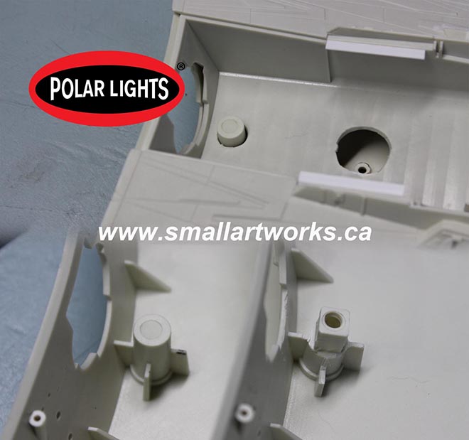
The first thing was to decide where the mounts needed to be. One obvious mount is the stand hole that is included in the kit so it can be bottom mounted. That part is not needed to change of course, and Round 2 thoughtfully provided a plug/hatch that covers up this hole for underside shots and for people who may not want to use the provided stand. Another mount already built into the kit is also a natural, the torpedo tube on the rear. The inner tube is a bit short, and must still contain the lighting inside, but I can make a post to fit for the purposes I need. The way the kit is designed, this torpedo tube will be strong enough to support the model when mounted from the rear. However, I needed to make the model mountable from the sides and the top. Because of the ship’s design it’s impractical to make a mount for the front. For shots involving the rear of the ship facing camera, it can be mounted from the sides, top or bottom depending on the angle needed. It seems, based on photos of the original model on stage, that these were the mounts used on it as well.
The stand hole molded into the lower hull section is deliberately quite deep and intrudes into the battery tub which is molded into the upper hull section (top), and I wanted to keep the upper hull removable until the model was at a near complete stage so lighting could still be installed. So I had to carve away some of the plastic so the square tubing I’d use for the armature would fit over it (bottom right) for support and without gluing. I drilled a hole in the top of that mount so that the hatch plug, which covers the stand hole when bottom shooting is required, could be pushed out from the backside when its removal is needed.
The armature, entirely glued into the upper hull battery tub section was made from Evergreen styrene square tube to fit the stand mount square stock (rather than cylindrical tube) so that the model would not have a tendency to rotate during set-up for shooting. Visual effects miniatures usually use much more robust armatures machined from aluminum or similar because the fairly large and heavy models must be kept rock steady during motion control filming, but this kit is so light that plastic armatures are good enough for my still-shot photographic purposes. You can’t really see them in the photos here but extra web reinforcement was also glued to the back of the square tube mating with the battery tub for added strength. Sections of the tub were also cut away to aid in wiring for the lighting as well as access to other sections during construction and/or possible servicing. The side armature had to be kept short so that it would not block the lighting for the forward bulkhead up front. The light will be blocked when the stand mount is plugged in but that won’t matter since I won’t use the side mounts when that section of the ship shows to camera. The top corrugated panel on the forward section of the main body was made separate in the kit, which is perfect to aid in painting and also act as a natural hatch for the top mounting point. A pair of glued on neodymium magnets hold it perfectly in place.
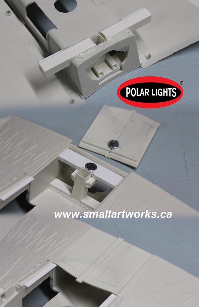
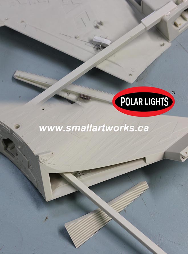
The problem with the side mounts is that, even though the grilles on the sides look big, they are at a very steep angle (about 60 degrees) so the side profile makes them very narrow. This had to be taken into account when planning the mounting rods and armature. But the problem was that the grilles on the kit were made to be cemented in from the backsides of the body before you attach the top. How to make the panels removable, yet easily replaceable when the model is finished? The answer can be seen here. First, the grille panels were modified so that they could be placed from the outside. Then a magnet was added to the inner surface. Why is there a screw? Because when you’re dealing with this kind of thing with all those crazy angles and no apparent mounting surface, you can’t be absolutely sure where things are going to fall. By putting a screw (which the hatch magnet will stick to) into a solid point deliberately set further back than you might anticipate, adjustments can be made if things don’t line up quite right.
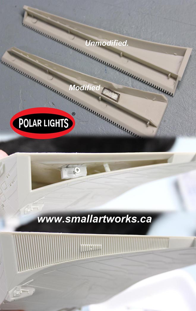
Here you can see the grille hatch unmodified and modified with trapping sections cut away and a magnet added. Then you can see the result of what the finished model will look like with the grille hatch removed and attached. They work fairly well. How do you remove the hatches? Because the screw is roughly in the centre of the hatch and acts as a crude fulcrum, you just push on one end, the other end pops proud and you can just grab it to pull it free. Another advantage in making those grilles removable is that I can complete some of the wiring even after the top and bottom body sections have been glued together. I still have the likely problem of light leaks around the removable grilles. I’ll work on that next along with a bunch of other things. More stuff to think through.
Looks easy doesn’t it? But with many things, it takes a lot of thinking to come up with the simple solutions to what look like complex problems. There are so many crazy angles to think of here that it seems very daunting at first, and you have to think ahead and carefully examine everything. Will it impede lighting? Will it stop the assembly from going together right? Will it allow for stand clearance? It takes time to work all that stuff out and you don’t want to make a modification that won’t work and become impossible to reverse. In fact I’d say ~90% of my time in building this model’s various modifications so far was spent thinking about how to do it and if there were better alternatives. In some cases maybe there are and I just didn’t think of them. The actual work itself takes relatively little time once you come up with the idea.
Meanwhile, if you future K’Tinga builders out there have a desire to mount your model from different points other than the standard bottom mount, maybe what I’ve done here can give you some ideas of your own.
Enjoy!
Very impressive work, Jim. Thank you for sharing with us. I love to see how people work out modeling problems like this!
YYYYAAASSSSSS!!! When will this lovely thing be released?!