Recommended Sites


Archive for the ‘Star Trek’ Category
Polar Lights Models: Klingon K’t’inga buildup process Pt.4
Continuing our series of guest blogs covering our brand-new STAR TREK: The Motion Picture 1:350 Klingon K’t’inga model kit…
K’tinga Build Part T’ree, Ready for Paint…
James Small, www.smallartworks.ca
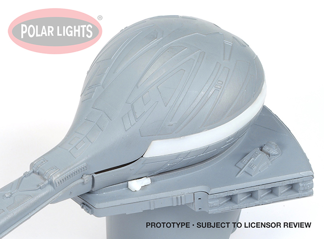
This is the last step in the main building of the various sub-assemblies and main assemblies, rounding the bend now, getting ready for the really grueling part, the massive paint job. Not a lot to cover here but I do want to point out a few things, and it was my “overthinking” of a lot of it that put me so far behind. The biggest problem I thought I would encounter was the fact that the main body section of the ship has to be all sealed up after lighting is installed, so I wanted to make sure I didn’t make any mistakes before sealing up the top and bottom main sections. The way the kit is designed I thought would be … “unfriendly” at this point because I usually like to be able to install or at least be able to access a lot of the lighting gear even after main sections are glued together. For example, I wanted to be able to install the engines AFTER the main body was assembled so as to make clean up easier. That’s why on two of the kits I cut large sections out of the insides of the battery box tub so that wires could be reached with tweezers etc, to pull them back in if they slipped out and went back inside the body after I had it all assembled. This is STILL a good idea but it turns out my concerns were unfounded. I spent far too many hours thinking this through and it turned out to be unnecessary for the most part. However a lot of other time was spent thinking through the special requirements for the modified photo model too (which still took too long!).
Note: The rest of this mostly applies to the stock kit, not the one I made with the modifications for photography.
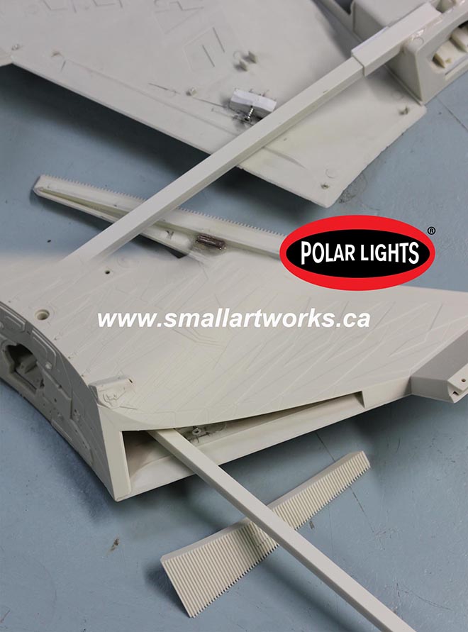
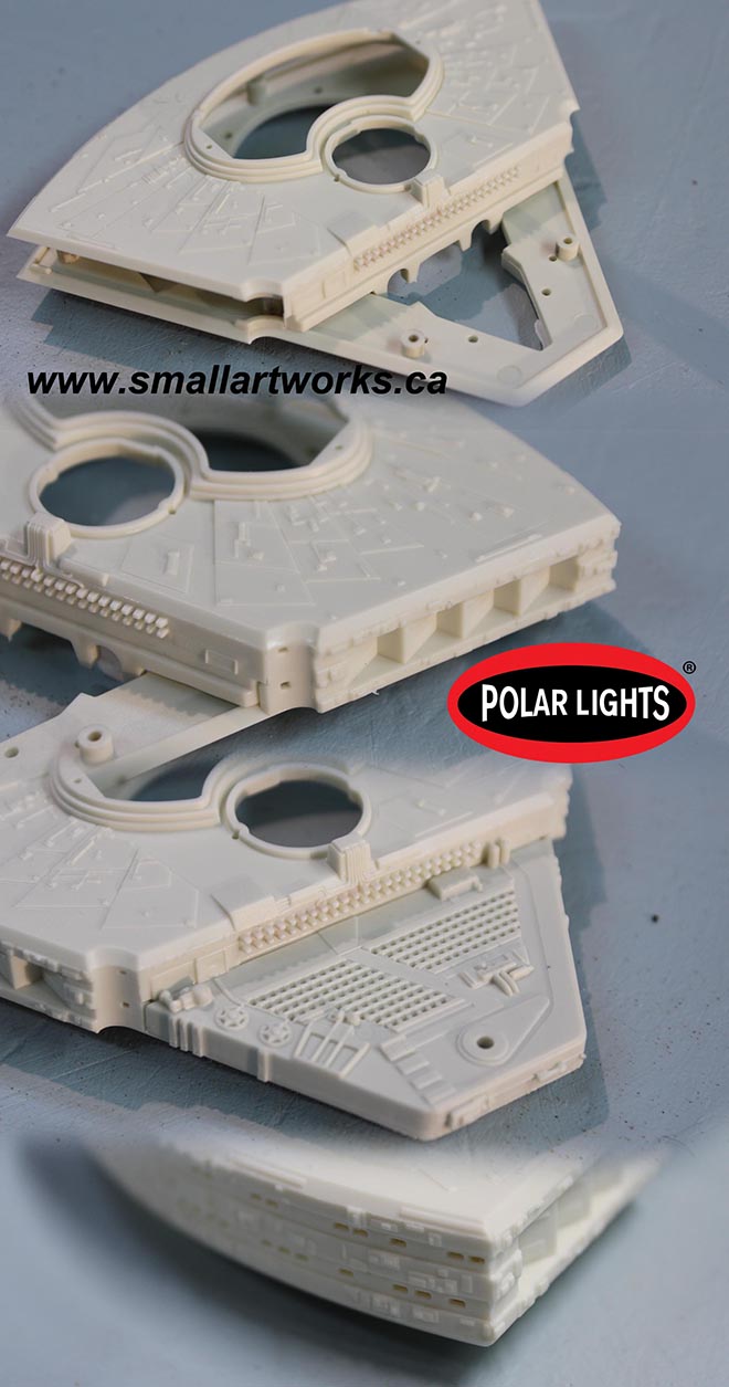
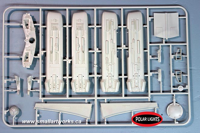
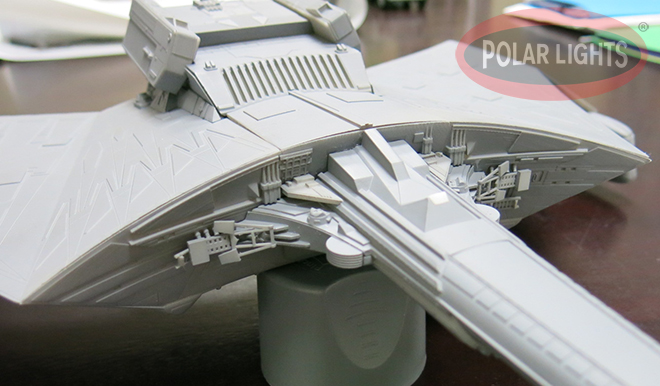
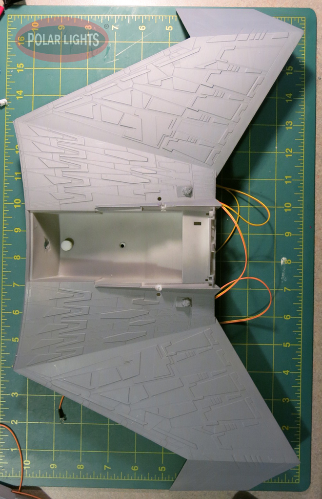
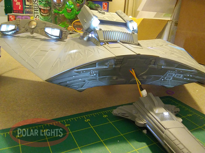
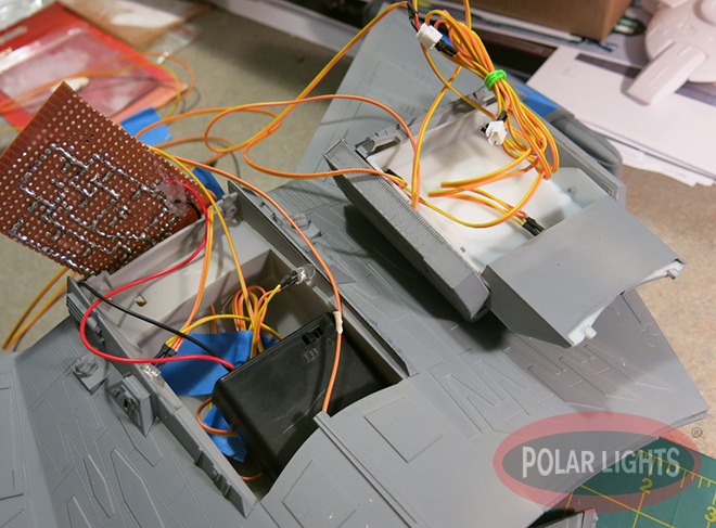
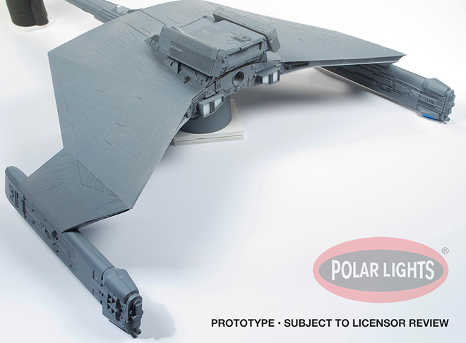
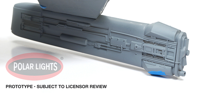
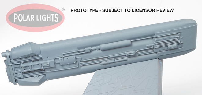
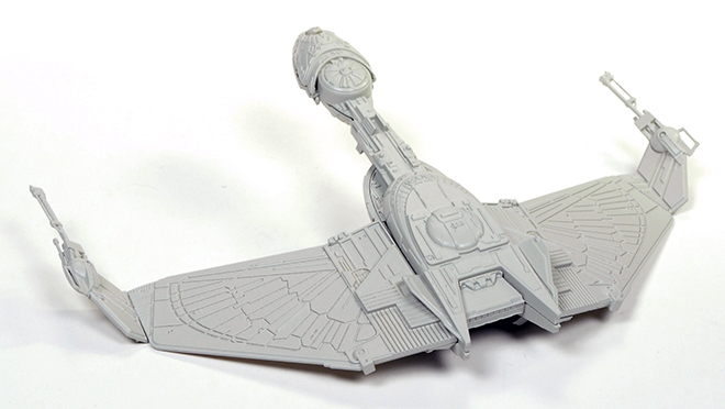
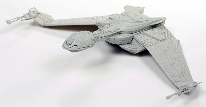
You assemble the engines with the lighting installed and the wires hanging out the top of the nacelles. Then you glue the finished engines to the bottom of the lower hull section pylons. You glue in the “wing radiators” at this time as well. With lighting firmly installed in place (AND TESTED!!!!) as shown, you can then glue on the top body section you see there, making sure to feed the wires in through the bottom hole in the battery tub. Once it’s all glued together, and if you are careful (remember that gluing hints article I referenced in a previous post) cleanup is really easy, no putty needed. With patience, it all goes together remarkably smoothly, everything lined up perfectly. Yes, it’s a bit of a chore to get all those locator pins to line up and all fall into place, but once you do, you just run a little liquid plastic cement along the seam allowing capillary action to do its thing. (I actually use a concoction of my own, a half-and-half mixture of lacquer thinner and acetone which is a lot cheaper and works better for me than the overpriced hobby glues and even dries quicker, but only works for joints where capillary action is used.) Press together, let the melted plastic ooze out between the joints and hold or clamp ‘til set. When dry, just use your knife to trim off the bead and you have a nice clean joint, no putty required.
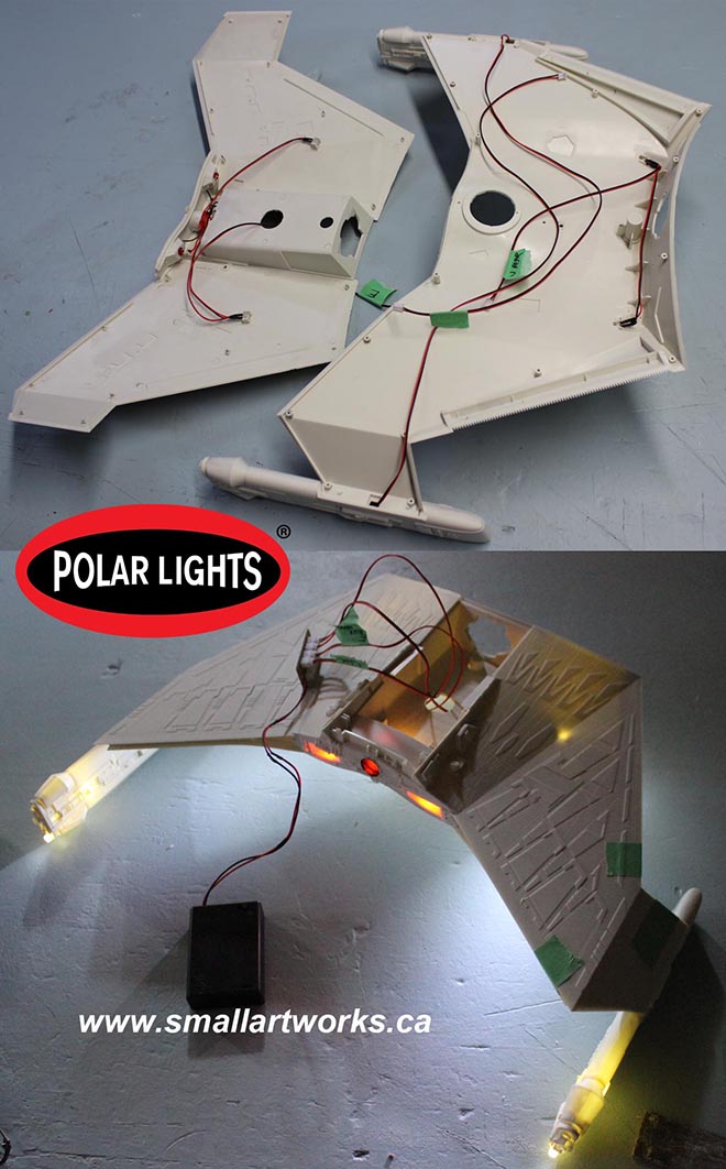
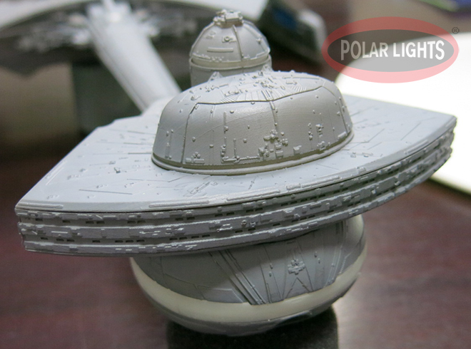
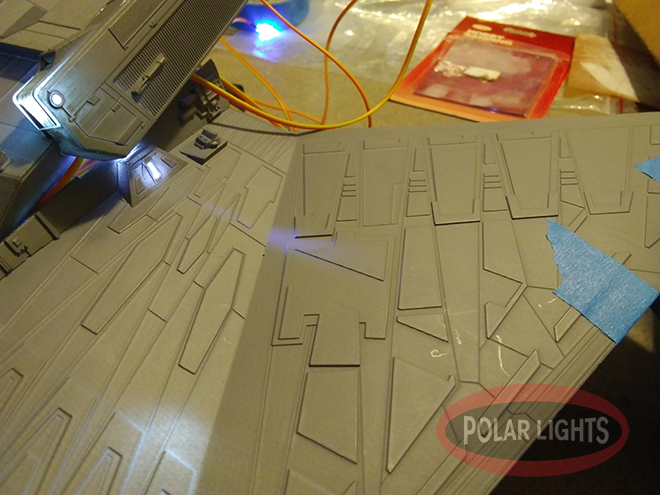
Yes, I know the plastic is translucent. Light blocking will be done by first coating the model (after careful masking) with Krylon gray primer which is effectively opaque. The colour coats will be applied over that. Also, some lighting elements are not yet installed. Those can be done after all the paint work is done.
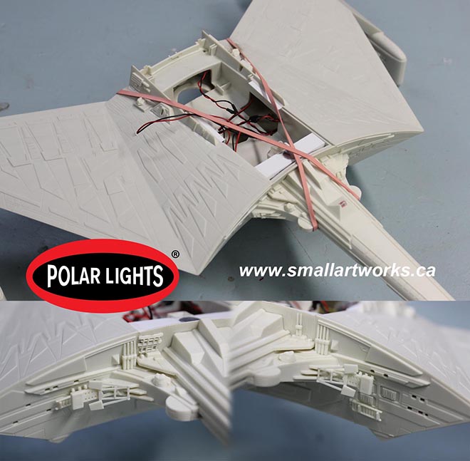
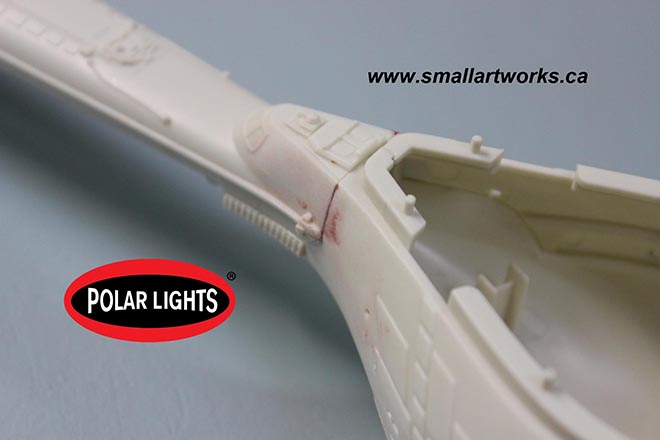
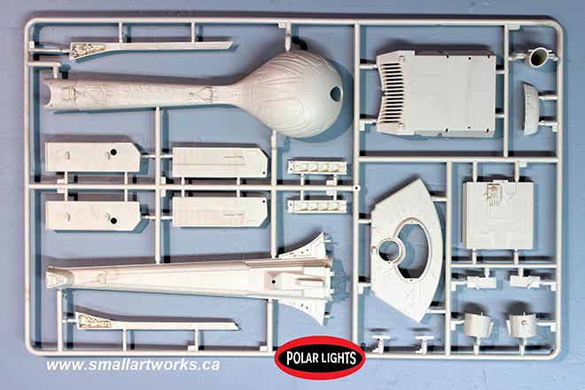
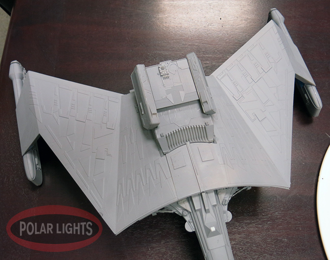
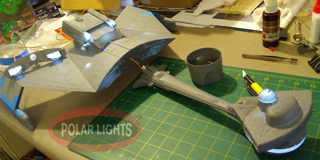
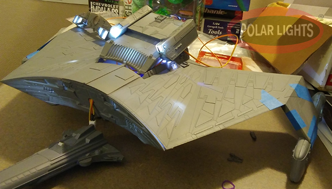
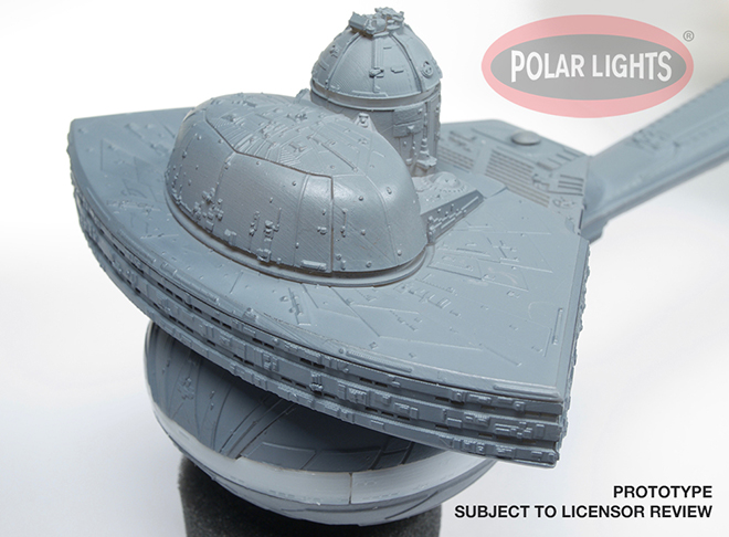
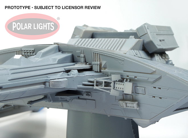
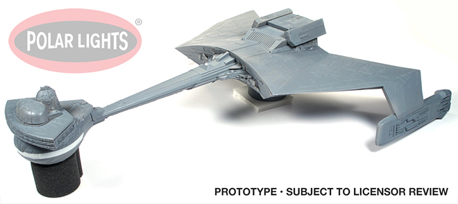
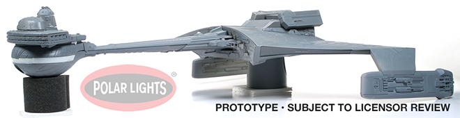
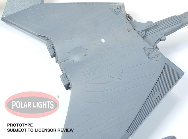
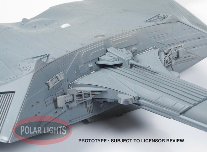
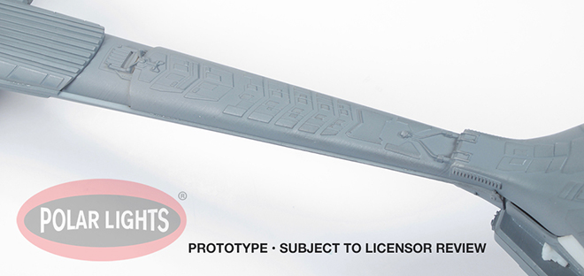
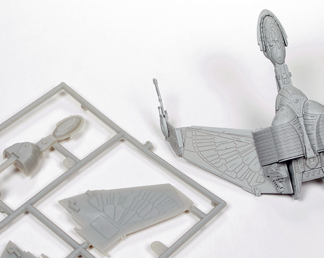
Next I glued the neck in place and held it to the body using elastic bands (modified model shown here but principle is the same for stock kit). Like joining the body together, just push it in place (everything lines up perfectly) then apply the thin glue along the edges and let it set. Once dry, I removed the elastics and was able to put on all the little greeblies that get attached to the bulkhead. I also installed the thin rear panels that go in between the wings at this time as well.
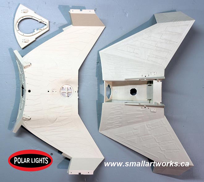
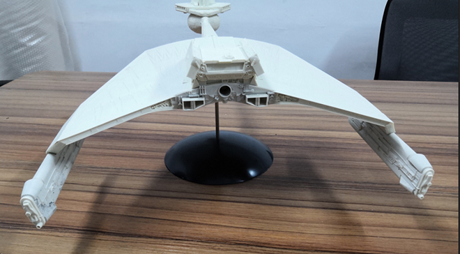
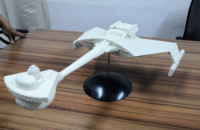
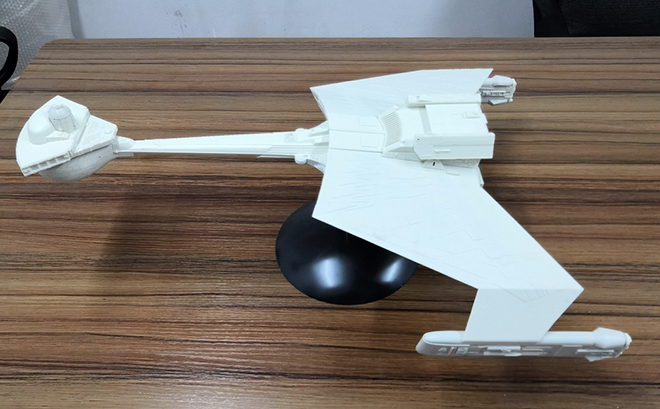
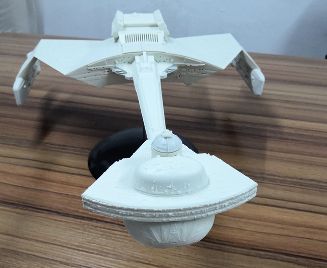
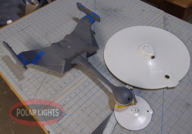
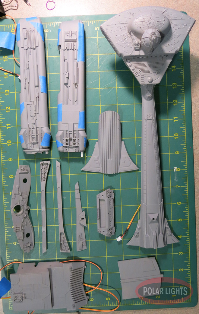
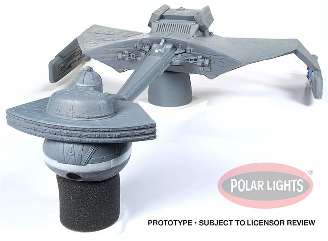
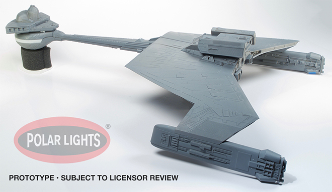
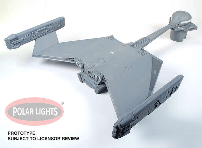
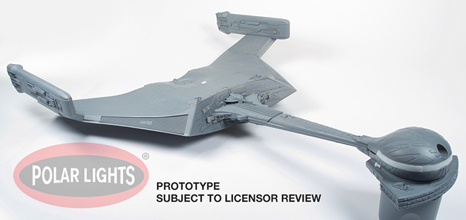
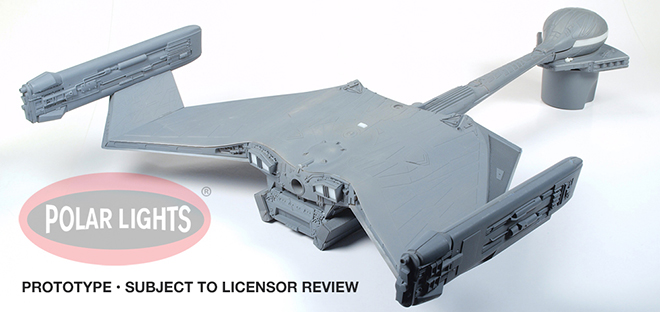
All three models’ sub-assemblies are finished (for the most part) and ready to begin the massive job of masking and painting. A few parts not shown here such as the top bridge dome will not be added until painting is finished.
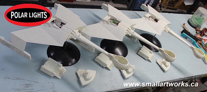
Due to time constraints to get the photography model done in time for Jamie to use for his box art and publicity material, I will now concentrate on just getting the modified model done first and will finish up the other two after the first one is all finished and photographed. Most of the time delay was my fault because I was overthinking so much of it.
Building this model is the easy part. Painting it will present some wonderful challenges… Hint: Most of the colours that were heavily researched by Jamie ended up being quite a bit different than I was expecting or appears to be in most photos! More on that as this build continues.
Polar Lights Models: Klingon K’t’inga buildup process Pt.3
Continuing our series of guest blogs covering our brand-new STAR TREK: The Motion Picture 1:350 Klingon K’t’inga model kit…
The K’tinga Build Part Deux, A Mounting Problem
James Small, www.smallartworks.ca
As I’m building three of these at once, I made the decision to modify one model to make it easier to photograph for the box art and publicity images. Therefore, this particular post deals primarily with the modifications I have done to this model to put stand mounts (AKA an armature) inside the model so that it can be positioned for photography at various angles, similar in principle to the way Motion Control miniatures were made for bluescreen filming back in the day.
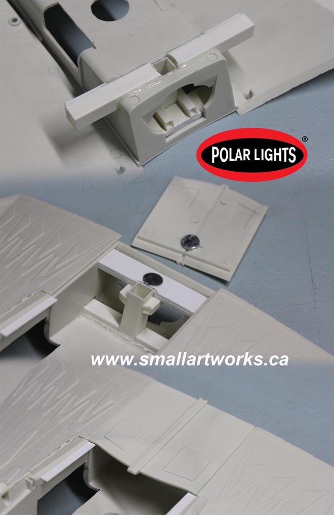
The first thing was to decide where the mounts needed to be. One obvious mount is the stand hole that is included in the kit so it can be bottom mounted. That part is not needed to change of course, and Round 2 thoughtfully provided a plug/hatch that covers up this hole for underside shots and for people who may not want to use the provided stand. Another mount already built into the kit is also a natural, the torpedo tube on the rear. The inner tube is a bit short, and must still contain the lighting inside, but I can make a post to fit for the purposes I need. The way the kit is designed, this torpedo tube will be strong enough to support the model when mounted from the rear. However, I needed to make the model mountable from the sides and the top. Because of the ship’s design it’s impractical to make a mount for the front. For shots involving the rear of the ship facing camera, it can be mounted from the sides, top or bottom depending on the angle needed. It seems, based on photos of the original model on stage, that these were the mounts used on it as well.
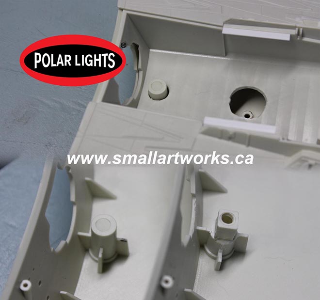
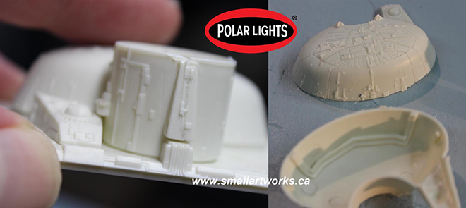
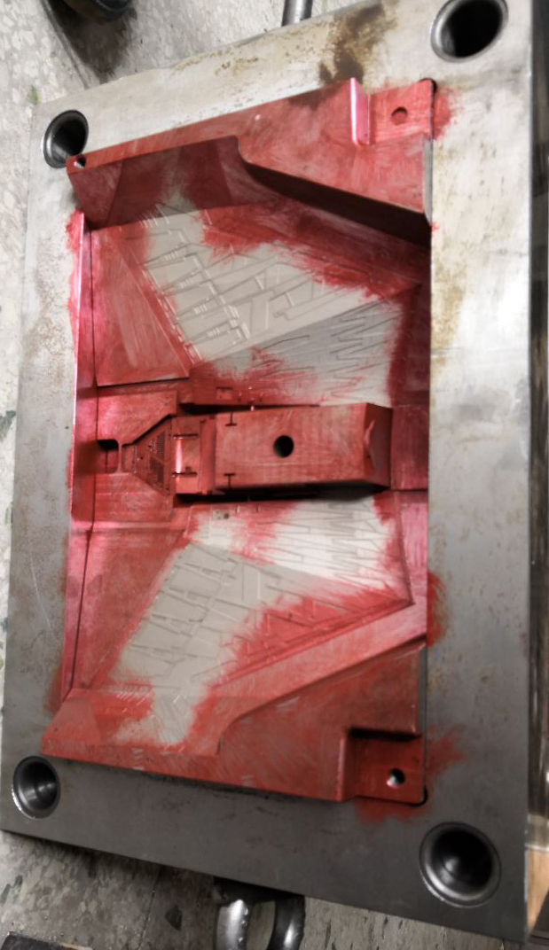
The stand hole molded into the lower hull section is deliberately quite deep and intrudes into the battery tub which is molded into the upper hull section (top), and I wanted to keep the upper hull removable until the model was at a near complete stage so lighting could still be installed. So I had to carve away some of the plastic so the square tubing I’d use for the armature would fit over it (bottom right) for support and without gluing. I drilled a hole in the top of that mount so that the hatch plug, which covers the stand hole when bottom shooting is required, could be pushed out from the backside when its removal is needed.
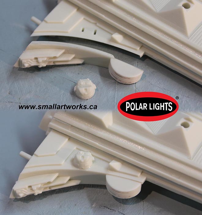
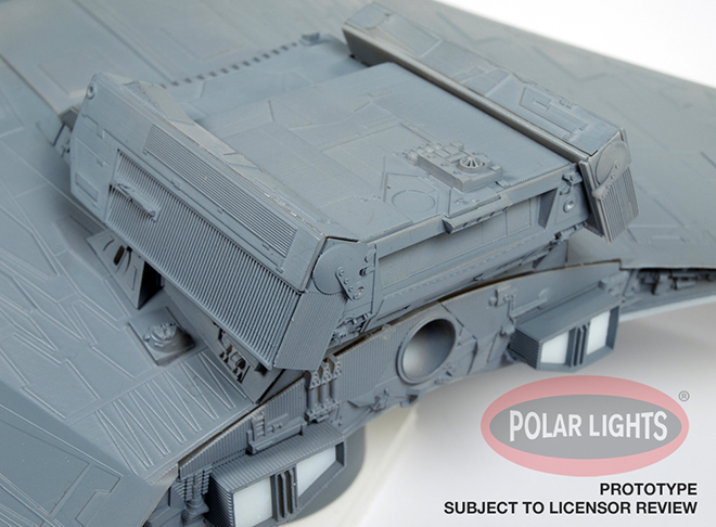
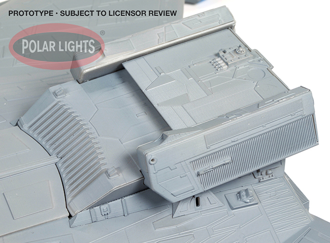
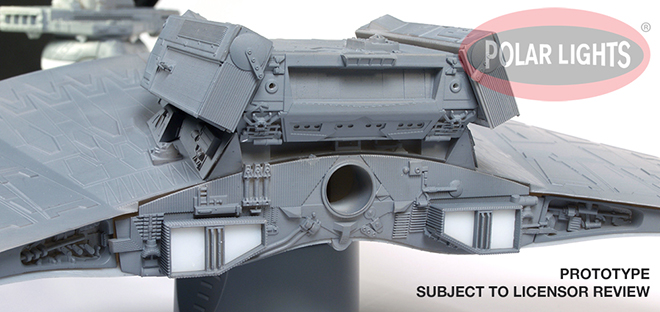
The armature, entirely glued into the upper hull battery tub section was made from Evergreen styrene square tube to fit the stand mount square stock (rather than cylindrical tube) so that the model would not have a tendency to rotate during set-up for shooting. Visual effects miniatures usually use much more robust armatures machined from aluminum or similar because the fairly large and heavy models must be kept rock steady during motion control filming, but this kit is so light that plastic armatures are good enough for my still-shot photographic purposes. You can’t really see them in the photos here but extra web reinforcement was also glued to the back of the square tube mating with the battery tub for added strength. Sections of the tub were also cut away to aid in wiring for the lighting as well as access to other sections during construction and/or possible servicing. The side armature had to be kept short so that it would not block the lighting for the forward bulkhead up front. The light will be blocked when the stand mount is plugged in but that won’t matter since I won’t use the side mounts when that section of the ship shows to camera. The top corrugated panel on the forward section of the main body was made separate in the kit, which is perfect to aid in painting and also act as a natural hatch for the top mounting point. A pair of glued on neodymium magnets hold it perfectly in place.
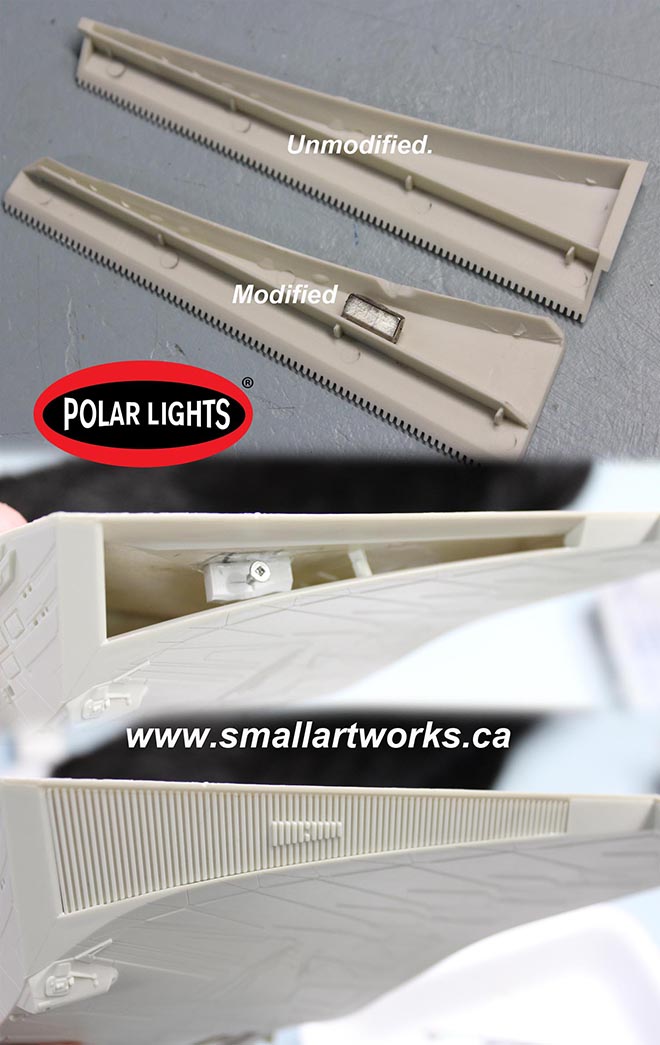
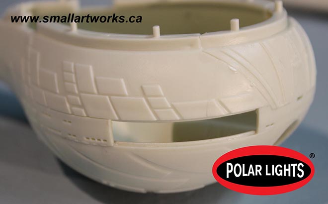
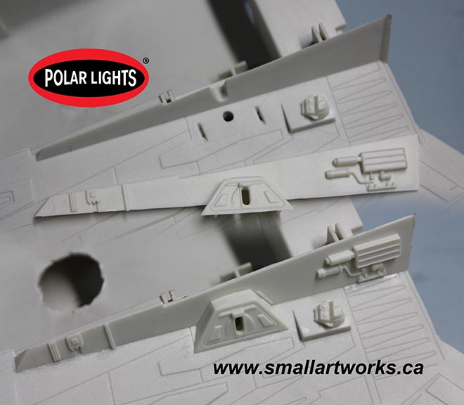
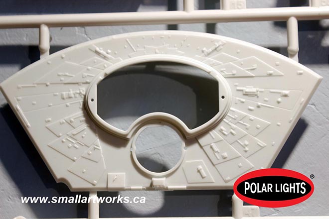
The problem with the side mounts is that, even though the grilles on the sides look big, they are at a very steep angle (about 60 degrees) so the side profile makes them very narrow. This had to be taken into account when planning the mounting rods and armature. But the problem was that the grilles on the kit were made to be cemented in from the backsides of the body before you attach the top. How to make the panels removable, yet easily replaceable when the model is finished? The answer can be seen here. First, the grille panels were modified so that they could be placed from the outside. Then a magnet was added to the inner surface. Why is there a screw? Because when you’re dealing with this kind of thing with all those crazy angles and no apparent mounting surface, you can’t be absolutely sure where things are going to fall. By putting a screw (which the hatch magnet will stick to) into a solid point deliberately set further back than you might anticipate, adjustments can be made if things don’t line up quite right.
Here you can see the grille hatch unmodified and modified with trapping sections cut away and a magnet added. Then you can see the result of what the finished model will look like with the grille hatch removed and attached. They work fairly well. How do you remove the hatches? Because the screw is roughly in the centre of the hatch and acts as a crude fulcrum, you just push on one end, the other end pops proud and you can just grab it to pull it free. Another advantage in making those grilles removable is that I can complete some of the wiring even after the top and bottom body sections have been glued together. I still have the likely problem of light leaks around the removable grilles. I’ll work on that next along with a bunch of other things. More stuff to think through.
Looks easy doesn’t it? But with many things, it takes a lot of thinking to come up with the simple solutions to what look like complex problems. There are so many crazy angles to think of here that it seems very daunting at first, and you have to think ahead and carefully examine everything. Will it impede lighting? Will it stop the assembly from going together right? Will it allow for stand clearance? It takes time to work all that stuff out and you don’t want to make a modification that won’t work and become impossible to reverse. In fact I’d say ~90% of my time in building this model’s various modifications so far was spent thinking about how to do it and if there were better alternatives. In some cases maybe there are and I just didn’t think of them. The actual work itself takes relatively little time once you come up with the idea.
Meanwhile, if you future K’Tinga builders out there have a desire to mount your model from different points other than the standard bottom mount, maybe what I’ve done here can give you some ideas of your own.
Enjoy!
Polar Lights Models: Klingon K’t’inga buildup process Pt.2
Continuing our series of guest blogs covering our brand-new STAR TREK: The Motion Picture 1:350 Klingon K’t’inga model kit…
The Ktinga Building, Part One
James Small, www.smallartworks.ca
Oh, OK, I won’t bother with the double entendres and food jokes with this one. Just the straight up dope this time, albeit not with a lot of pictures. Most of my time was spent just looking through the parts, test fitting and comparing them to the CG model (used for the tooling) and gaining an understanding of what goes where and when certain parts should be assembled and which ones should be left off until lighting and painting can be done. That’s the way it goes when you’re building a kit (actually three of them in this case) for the first time without the instructions that will be included in the final kit! I’m also doing what I can to document it for both this blog and for possible ways to make minor improvements in the kit as we go along so such changes can be incorporated into the kit as you people will be buying it. The test shots have been done, but small improvements will still be made, which is why they are called TEST shots. Also, I wanted to actually get PAST the points covered in this blog to make sure I covered it all needed before the next. Lotsa back-and-forth with this one.
First, I will let you know that I will be describing this build with the lighting kit being installed, as this is the most comprehensive way to do it. If you will NOT be installing the lighting (why would you NOT want to light it up???) then you can take obvious shortcuts, but I will not deal with those shortcuts here.
I wanted to assemble as much of the sub assemblies as I could before the lighting or painting needed to be applied. That part turned out to be a bit tricky as this is one of those models you need to do a little bit of each as you go along. That means there will be assemblies you will build, then you will install SOME lighting, then you will build some more, do a little painting, then put in more lighting, then more building, and back and forth and so on until it is finished.
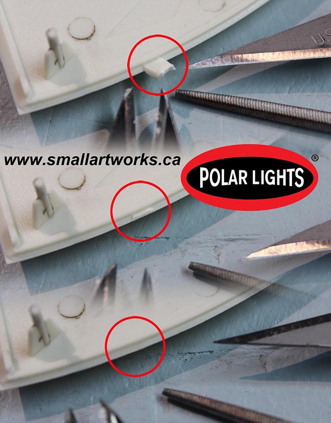
The next thing I want to talk about is how to properly remove the parts from the runners. There are a lot of delicate corners and edges on this one, but if you are careful removing the runner gates, no putty will be needed to smooth things out or hide joints. The pic FIG 1 shows the procedure. First, cut the part from the runner while still leaving a good chunk of the gate attached to the part. Then, using your nippers or a sharp blade, slowly whittle off the remaining nub. Finish the surface off using a needle file. The better you do this on EVERY PART of the model, the better the parts will fit.
The first parts I assembled were the “Cobra Heads” of all three models. When the above parts preparation procedure is followed and you take your sweet time assembling, the parts fit together absolutely perfectly with no puttying needed and almost no cleanup except for a slight scraping of the edges with a sharp knife after the glue has set. The procedure used to properly glue these parts was covered in an article I did years ago for Round 2’s now defunct “Workbench” page, but can be viewed here on the Small Art Works hosted CNSM page for those of you who would like a refresher.
http://www.smallartworks.ca/CNSM/VS%20build/Pretty%20In%20Mauve.html
Note in FIG 2 that no putty was needed to successfully assemble the parts which are well engineered. I’ll let you in on a little secret here. Although some modelers demand such amenities (which is why Round 2 provides them), I deliberately did NOT use the clear window parts supplied with the kit that would normally be installed behind the outer hull window panels. I find that too difficult to work with (though some modelers have no problems with it). I instead will leave the windows unglazed, then after painting I’ll fill the window holes with Testors “Clear Parts Cement and Window Maker”. Microscale makes a similar product called “Micro Crystal Clear”. In a p[inch white glue would even work but white glue is not as transparent. Then, when the model is finished, a clear dullcoat spray will fog the windows enough to provide properly diffused lighting from the LED’s inside.
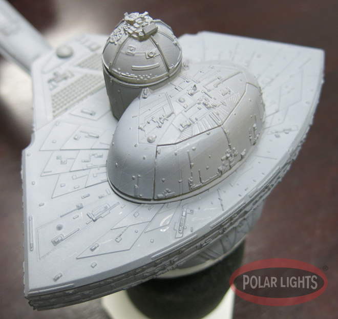
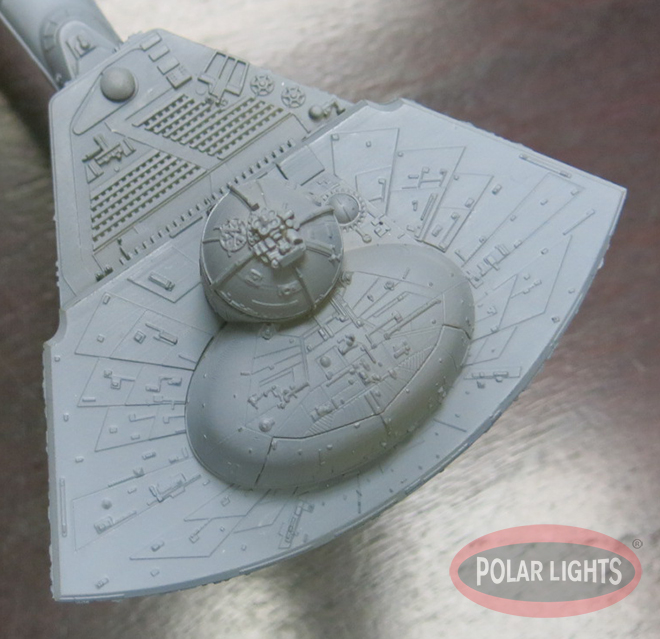
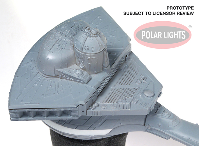
Because it called out to me, I quickly assembled the bridge cylinder and the elliptical section that sits on top of the cobra head because those were so easy to do. The elliptical section glues together so well that the gap is unnoticeable as it falls on a natural panel line. Then I glued the cylinder to the cobra head section and noticed a GAP! OH NO! Naw, false alarm. The gaps that you see in the pictures are actually supposed to be there. It’s likely a result of the original VFX miniature being made that way, because the bridge section was made removable for maintenance and so, yes, those gaps are authentic! So before everyone complains, that is NOT an error of the kit! See FIG 3. Very little clean up was needed between the two cylinder halves.
The next thing I assembled was the lower part of the head which I call the “bulb”… because… duh… that’s what it looks like. The best way to go about this (hey, I had three tries, eh?) is to cement the forward part of the top half of the bulb together with the two sides of it so that all three parts of the top half of the bulb are properly aligned. Do this while continually testing (but not gluing it) to the cobra head section that will eventually be permanently mated with it. Then, when the glue has set, cement the top to the bottom half and then glue the window sections in place as shown in FIG 4. The torpedo tube was also glued in at this time as well. Any slight overlap of the window section relative to the bulb section can be easily trimmed down or disguised by the fact that the entire window section will be painted black, so the parts seam line will be naturally disguised by that very obvious colour difference. This deficiency is being worked on by the factory to improve the fit. Also, a decal for the darks tripes that go over the windows will be provided. The bulb is NOT glued to the cobra head yet. That will be done after the model is painted and the lighting is installed.
Next I glued on some rather insignificant detail parts (FIGS 5 & 6) because there were bits that would need to blend into the finished model which did not need any special treatment and could be added without being detrimental to the lighting system that would later be installed or impede paint work.
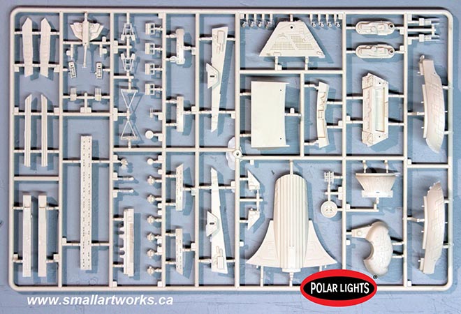
The sharp eyed observer will notice the direct tie in to Star Wars on this model. Yes, the foot pad from the R2 D2 MPC model kit was actually used on the original filming miniature exactly as you see, tying Star Trek and Star wars together the way only ingenious model makers can! In this case, R2’s foot was used as the vehicle from which the Klingon insignia spotlight would shine. See FIG 6.
I did find just one spot that needed some putty between the joints, but it’s a very easy fix. See FIG 7
Quite a bit more has been done to the model since these photos were taken which will be covered in the next installment.
Polar Lights Models: Klingon K’t’inga buildup process Pt. 1
Just like Santa takes a vacation the day after Christmas, model kit brand manager Jamie Hood has dropped off the goods (in this case, that means K’t’inga test shots) and is off on vacation. In the meantime, Round 2 consultant and model builder Jim Small will be sharing the process of building our display model that will be featured on our box art and will be making appearances at shows like Wonderfest next year. We hope you are hungry for this series of blogs.
Three Delicious Servings of Styrene Goodness!
James Small, www.smallartworks.ca
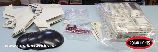
Well, well, well!!!! Look at THIS!!! A wonderful plate of appetizers came to the carnivorous lair of Small Art Works today, filled to the top with three test shots of the next fantastic model kit release from Round 2 and Polar Lights! I’ll be building all three of these at once, assembly-line style for the most part. All will be lit, but one of them I plan to try and install mounting points on the sides, top bottom and rear of the ship the way the studio model was done, which will aid in the photography I’ll need to do for publicity photos and box art etc. Only one lighting kit was supplied by the factory so I’ll have to scratch the lighting for the other two. Several parts had come loose from the runners and were put into ziplock bags. Each of the three main large sprues shown measure over 17” x 11” in character, so that gives you a good idea of how big this model will be!
I’ve taken some pictures of all the sprues here so you can see for yourself the delectable ingredients supplied with the upcoming kit, the loose ones were put in place into the runner locations they came from to show you. The parts are very crisp and clean, panel lines are perfectly recessed to match the original and the fine seasoning of detail is very sharp! This kit is exactly half the size of the actual filming miniature as seen in Star Trek, the Motion Picture. Yes, this kit really IS as good as it looks to be and will make a satisfying full course meal for all avid Trek fans!
As I write this I have examined the parts overall and have tested the lighting system. Next I will be studying it all to figure out the best way to cook this thing and work out assembly and painting strategies. Likely I will be looking for the “quick” subassemblies to get out of the way first.
The biggest challenge of this kit will be the tasty paint work… the “icing on the cake” as it were, as there are many colours in this menu which will need a LOT of masking! Jamie will be supplying me with the paint colour information as he’s probably THE world authority on this model by now because he’s been preparing for this feast for quite a few years and has worked tirelessly to make it as complete and accurate as possible! He knows more about what goes into this dish than just about any other galaxy class chef at this point.
I’m going to really enjoy preparing these meals over the next while, and I’ll post my progress here as I go, so bookmark “collectormodel.com” and keep checking back! You may find some of what I bake here a helpful series of hints to supplement the main recipe that will satisfy your taste buds when you place your order!
Let’s get ready to dine with the Klingons! (Bring extra napkins, and yeah, I was hungry when I wrote all this.)
EjIMBo
![]()
See how crisp and clean the fine detailing is? Delicious!
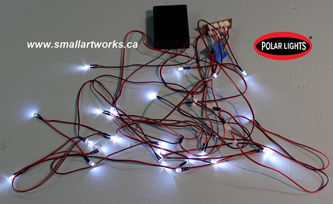
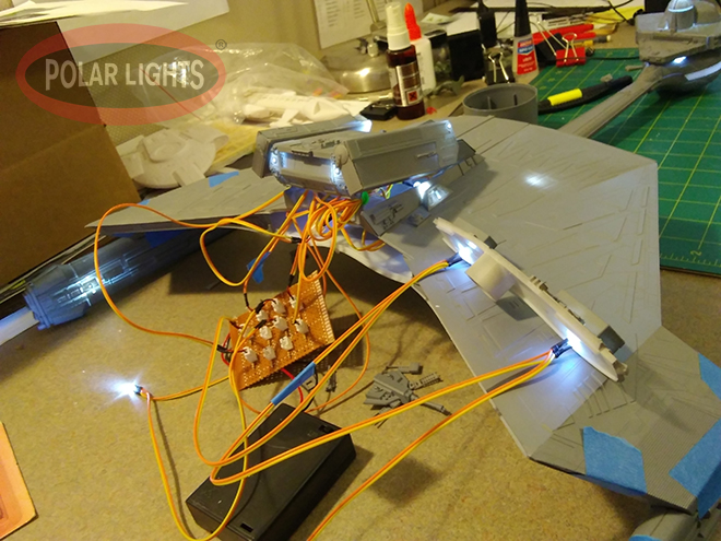
Quick-and-dirty testing the lighting system. Looks like a mess here but it’ll be worked out. Two of the bulbs flash which is why one is off as it blinked during exposure. All lights work perfectly.
Higher resolution pics can be found at the Small Art Works Facebook page here.
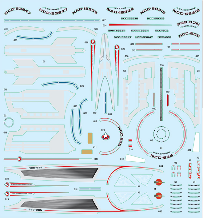
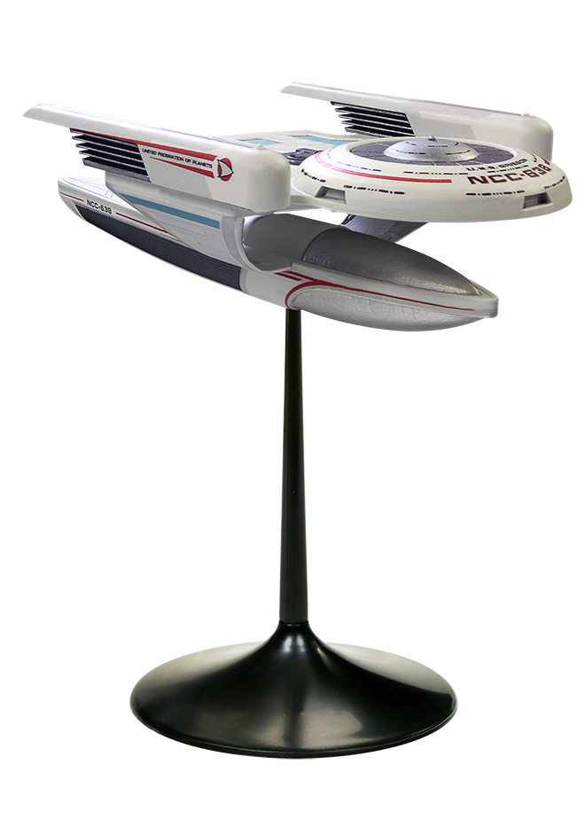
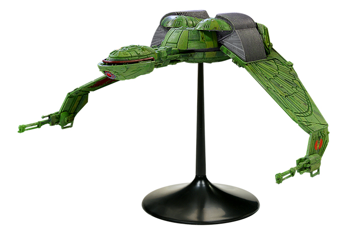
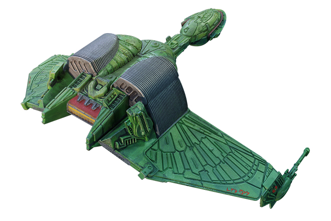
Star Trek Models: Klingon Bird-of-Prey & U.S.S. Grissom
[UPDATED to show decal sheet]
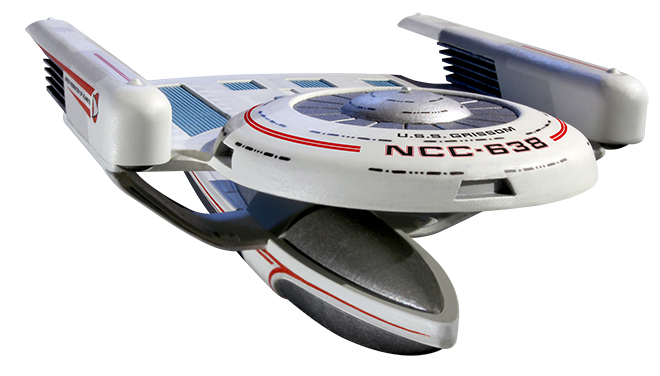
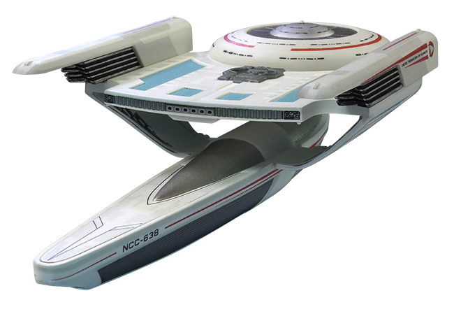
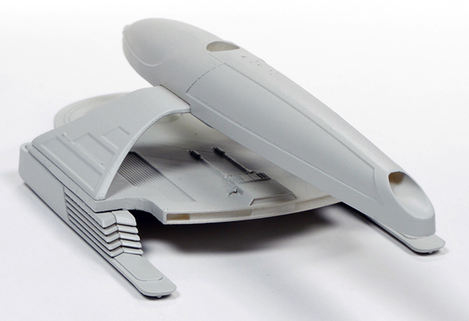
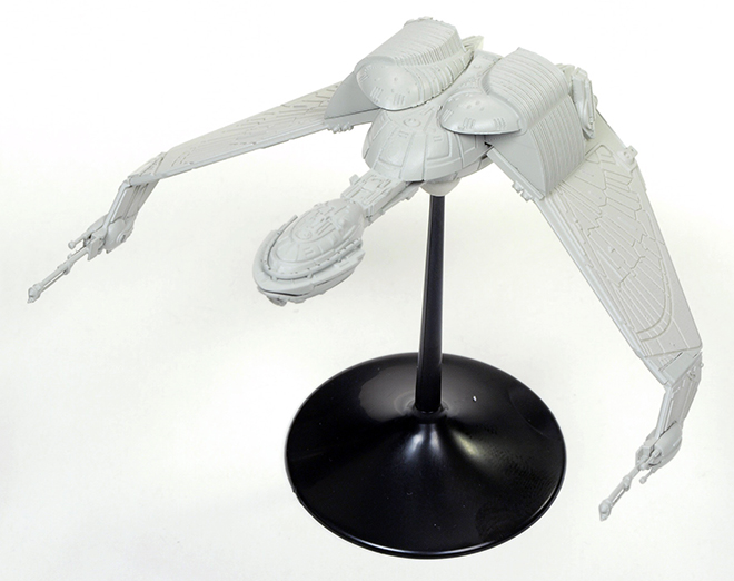
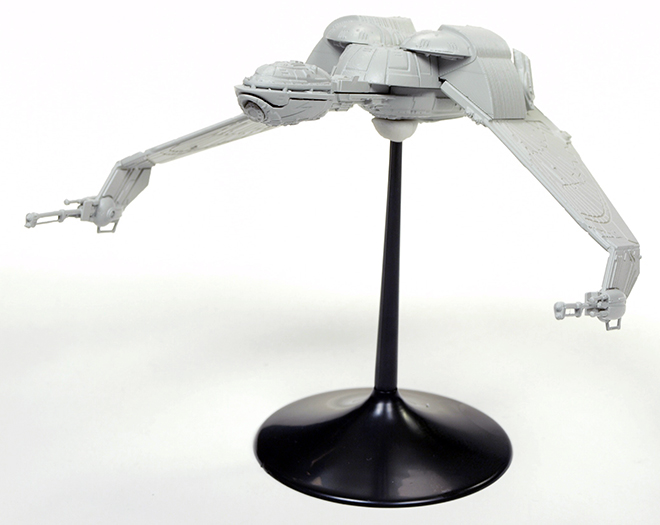
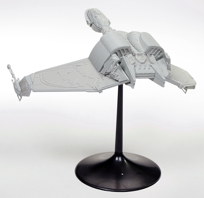
In the midst of summer activities and staying at work on our new Klingon K’t’inga kit, we don’t want to overlook another exciting Polar Lights kit we have in the works – the Klingon Bird-of-Prey and U.S.S. Grissom 1/1000 scale snap-together kit. These are two fan-favorite ships and the Grissom is getting produced as a kit for the first time ever thanks to the numerous requests we’ve heard over the years. These two kits make a fine addition to our line or 1:1000 scale snap kits.
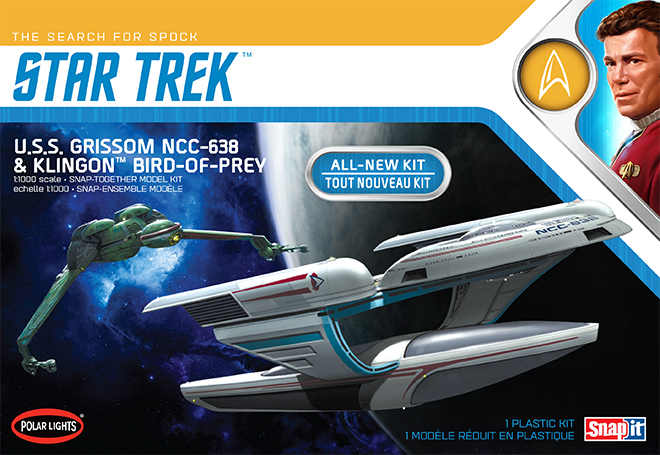
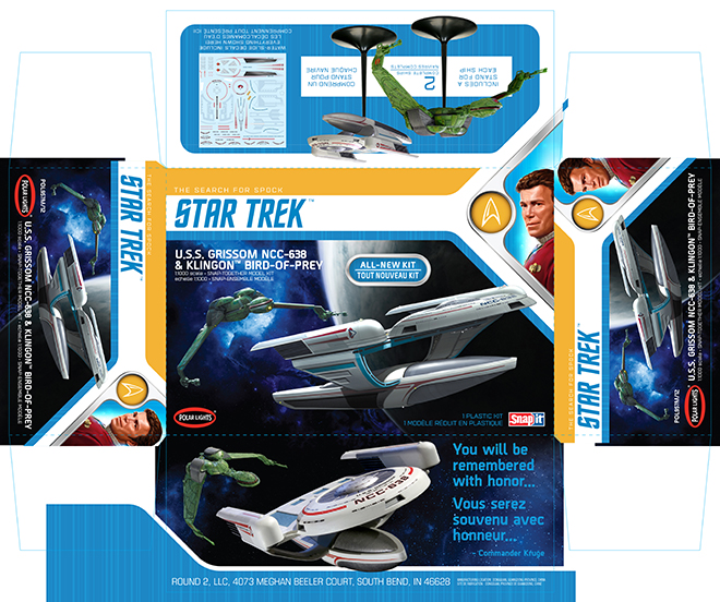
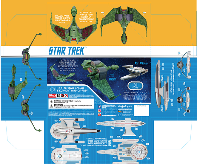
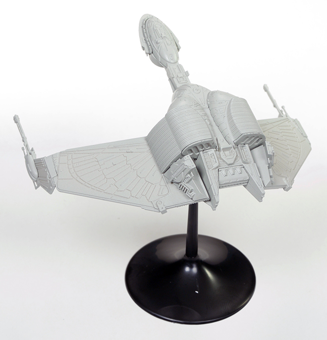
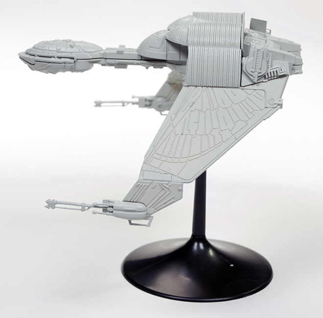
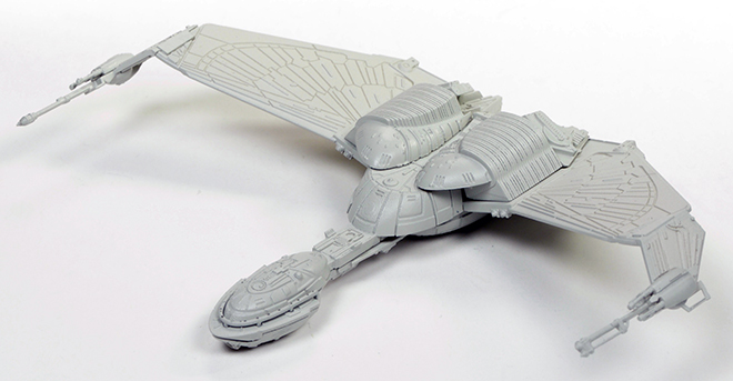
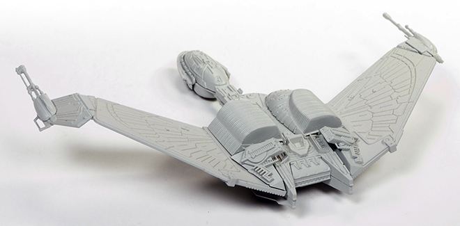
Here is a look at the packaging which features box lid artwork by Star Trek Production Artist, John Eaves. The box utilizes the updated Star Trek style guide and as has become our habit, we show a full color decoration guide on the sides of the box bottom. Both models come with stands and the Bird-of-Prey can be assembled with its wings up in cruising position or down in attack position.
After some delays in the tooling and test fit phase the kit is in production now, and product should arrive around the end of August.
Polar Lights Models: Klingon K’t’inga test shots are coming!
It is great to see all of the attention our new Star Trek: the Motion Picture 1:350 scale Klingon K’t’tinga model is getting. Folks have been oohing and ahhing over the photos of the new mockup we showed off at Wonderfest. Test shots are shipping and they should arrive by the weekend. I just wanted to share a small teaser and fill you in on what we’ll be sharing in the next couple weeks.
Jim Small is our go-to buildup guy. He is a consultant on virtually every sci-fi kit we put out. As usual, I am super-busy and Jim is willing to share his progress on the test shots and buildup as he works on it. So we will be posting his progress here and simultaneously (give or take a few minutes) on his Small Art Works Facebook page. He’ll get more in depth with it than I would be able to do anyway.
I might pop in to show photos of my test build. I also hope to squeeze in some time to discuss the color research we’ve done on the ship and share some of that… and maybe even get some help or feedback on finding some specific paint colors to match. More on that soon (hopefully).
But now… more of these…
And some of this! (from our friends at the factory) It is getting real, folks!
Polar Lights Model Kits: Quick update
[UPDATED] I know it has been a while between posts and that is due purely to getting super-busy. (It happens all too often… but that’s a good thing, no?) I just received something to share that is worth interrupting my busy workday, but it will need to be quick. But while I am writing, a few updates…
POL952 U.S.S. Defiant – Arrived at our warehouse this week. You should be seeing it available from your retailers in the next couple weeks.
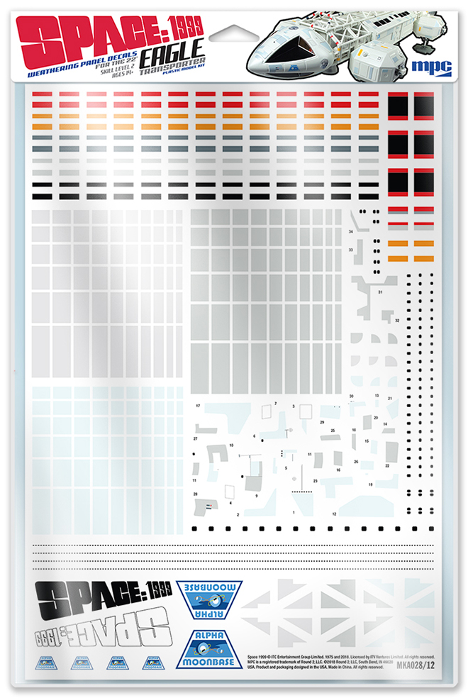
MKA028 Eagle Weathering Panel Decals – I totally overlooked the announcement of this. It is essentially the same sheet we included in the Brian Johnson special edition we did of the 22″ Eagle kit. These should be available in mid-late June.
MPC881 Hawk – Should be available from your retailers by the end of June.
POL957 U.S.S. Grissom & Klingon Bird-of-Prey – Due to delays in getting the test shots refined, this kit is slipping back to August. The shots look pretty good, but refining fit for a snap kit is always tricky. Packaging for the kit is being worked on now and we’ll show that off soon. We are thrilled to announce that it will feature a box lid illustration from Star Trek production designer John Eaves!
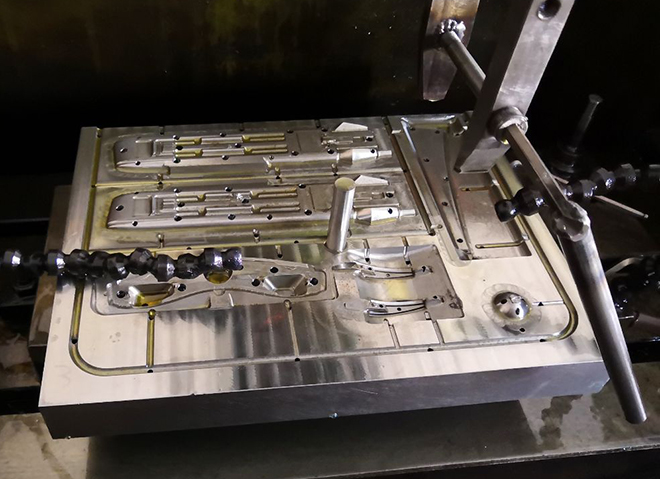
POL950 Klingon K’t’inga – Good news/ bad news … Delays in refining the CAD has caused this to slip all the way back to October. That’s only part of the bad news. The other is that this delay also pushes the test shots past Wonderfest by a few weeks. So we won’t have a fully built and painted model on display. On the good news side, the revisions were definitely worth it, because the factory was able to supply a second mockup based on the final CAD data and it has been assembling like a dream! We will have a new primered prototype with the lights on to show off at the show along with all of the buildups of the rest of our new kits mentioned above. We really look forward to seeing everyone at the show!
Now on with the thing I mentioned. A behind the scenes look at the K’t’inga nacelle tooling being created…
Polar Lights Models: More K’t’inga goodness
It has been a great week. Thank you for such an overwhelmingly positive reaction to our K’t’inga kit announcement. We knew Star Trek modelers everywhere would love it, because you’ve made it perfectly clear how badly you wanted it. But still, the reaction was better than we could have predicted. A set of test shots for another kit did not show up this week as expected, so we’ll share some more images and info on the K’t’inga kit.
First, let’s answer some questions.
How long is the model? – In our excitement last week, we neglected to mention the length of the model. It will be 24″ long and nearly 18″ wide. Some have suggested that seems small, but the length was based on existing information that was widely accepted. Could one debate that it should be longer? Sure, but in process of developing a kit of this stature, weight has to be given to tooling space and the cost that incurs. So, it comes down to A) we can make an argument that at 1:350 scale the ship would be 24″ long and B) we can afford to tool up a 24″ long K’t’inga. We can’t afford to do a bigger one. If you disagree with the scale, you can call it what you want. No hard feelings.
Yay! Now when can we expect a 1:350 D-7, Reliant, 1:1000 Enterprise-D or 1:32 Galileo? – Your guess is as good as ours. Our history speaks for itself. So, don’t expect them soon. But, let’s consider this… what would there be interest a Galileo without a full interior? Deleting the interior would make it an affordable option at some point. No promises one way or another, but feel free to offer feedback on that notion.
It looks like the white parts in the mockup represent the clear parts in the kit. Is that how you plan to address the windows on the bulb? – For the most part, the unpainted resin parts in the mockup represent parts that are to be included as clear parts in the kit. However, part of the purpose of doing a prototype is to see what you think will work actually works in practice. After seeing the cobra head windows knocked out, we are considering knocking windows out in the bulb. Those windows will be tiny. A clear backer will be included, but if you want those portholes to filled to present a flush face window, we will be suggesting liquid window maker to fill them.
Is the hull plating symmetrical? – On the kit yes, on the filming miniature not so much. It mostly was, but not 100%. We are going to KISS it. (Keep It Simple Stupid)
What will prevent neck sagging? – Good engineering. The mockup had no locators whatsoever. We will be sure we have accounted for the possibility of the neck to sag or break at the bulkhead. It is a lot like the pylon issue on the 1:350 TOS kit. We know well enough to figure it out.
Will ALL the detail be maintained? – Yes and no. The work in the mockup had not fully taken into account tool drafting. In some spots details might be compromised, or we will break parts up a bit differently to get as much detail as we can. In some instances we aren’t satisfied with the result and we’ll see if the factory can find a way to do better. I predict we will be able to maintain about 95% of the detail by the time it is done.
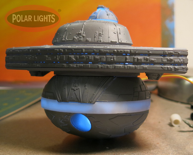
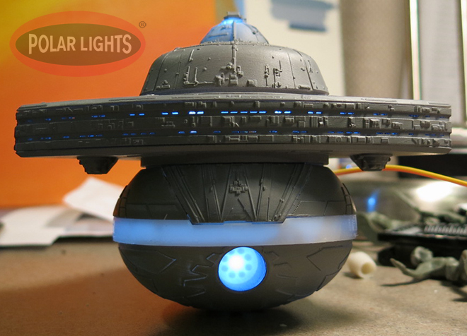
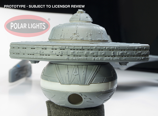
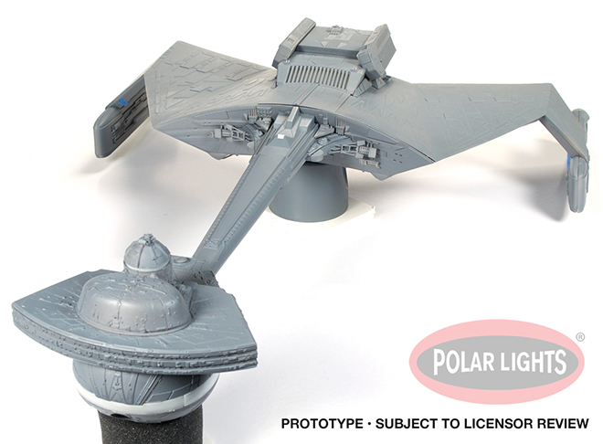
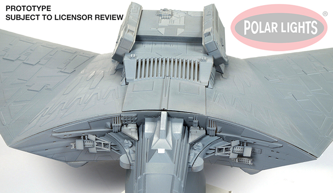
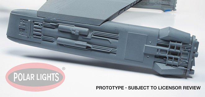
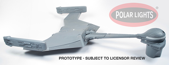
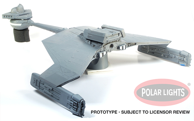
The photos below will show some “behind the scenes” shots of the mockup in various states of assembly. They should provide a decent sense of scale. It also gives a preview of how the light kit will look. A thin coat of primer wasn’t enough to hide the light, but we needed to install as much as we could to be sure we had enough light where we needed it and adjust as needed.
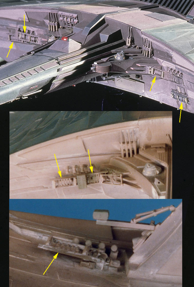
Lastly, you’ll see an image with yellow arrows pointing to some parts on the filming miniature. As most people realize, many of these details were pulled from plastic model kits available during production of the film. Our consultant team identified nearly all of the “greeblies” that were used. This is the most noticeable piece one has evaded our attempts to identify the kit (or thing) it originally comes from. If you know, please let us know. We used the limited reference we have to draw up the part. If we can make it more accurate, we would like to.
Star Trek Model Kits: All-New 1:350 K’t’inga Model Kit
To say the least, we’ve teased this announcement for too long already. So without further ado… THIS!
Yes, Round 2 has been developing a 1:350 scale Klingon K’t’inga as featured in STAR TREK: The Motion Picture! This is one of the kits we have been asked about since Round 2 got into the model kit business 10 years ago. Rumor and/or speculation has been that development of this kit started back at Playing Mantis before Polar Lights was obtained by RC2, but I’ve found little to no record of that in the development notes I’ve encountered in my role as the chief sci-fi kit product developer here at Round 2. We have been working with Charles Adams for well over a year now on this project. He has supplied the CAD model for the basis of the ship. Steve Neisen is also consulting on the add-on model kit bits that were used on the original filming miniature. Jim Small is also involved in the development and will be building our publicity model. I have been discussing with Charles the possibility of writing some guest blog entries about the ship to share some of his years-long research into the model.
The photos show the mockup (prototype) of the kit and it needs a little bit of explaining. The factory has been working over Charles’ CAD work and adding details that he would have supplied as model kit parts on his own studio scale model. We sent kit parts to the factory to scan. In some instances they used scans and in some cases, they tried to rebuild them from measurements. In some cases you can’t tell the difference. In some cases you can. Our partner factory in China recently took their annual holiday for Chinese New Year and did their best to get the mockup to us before leaving for their break. They were up against the ship date with some details needing adjustment and with minimal engineering to fit the parts properly together. No locator pins, etc. This was a freshly printed rapid prototype and they had no time to test fit or make adjustments, so I’ve been doing my best to cobble it together. have no fear of gaps and obvious glue bombs. All will be revised well before production.
Let’s see what else… answers before there are questions…
- The target retail price will be around $100.
- Yes, we will be putting out a light kit. We’ll show some candid pics of that in a post later on.
- Yes, we plan to do a ST:VI Kronos One version later down the road as long as sales on this first release supports that notion.
- The kit is currently scheduled for September release. Yes, that soon. If we can stick to the schedule, that would mean we’ll have a test shot built to display at Wonderfest in June.
- Distributors can look for this product to appear on our next price sheet which will go out within the next week. (By 3/9)
For now, enjoy a look at the mockup. We’ll put higher res pics on our Facebook page. Feel free to ask questions here and I’ll come back and answer a slew of them all at once in a future post.
Qapla’!

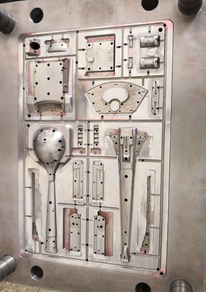
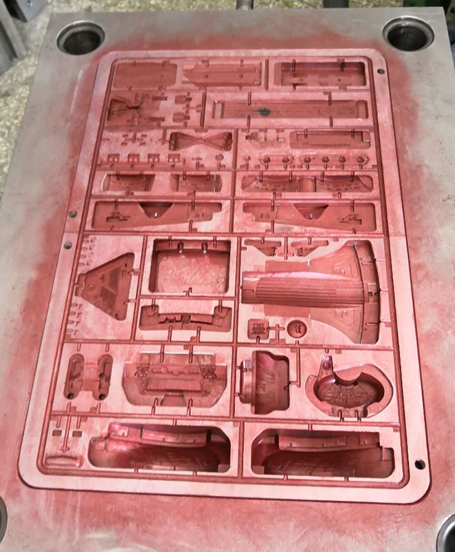
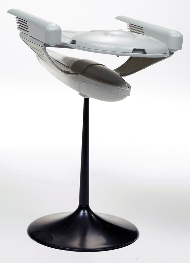
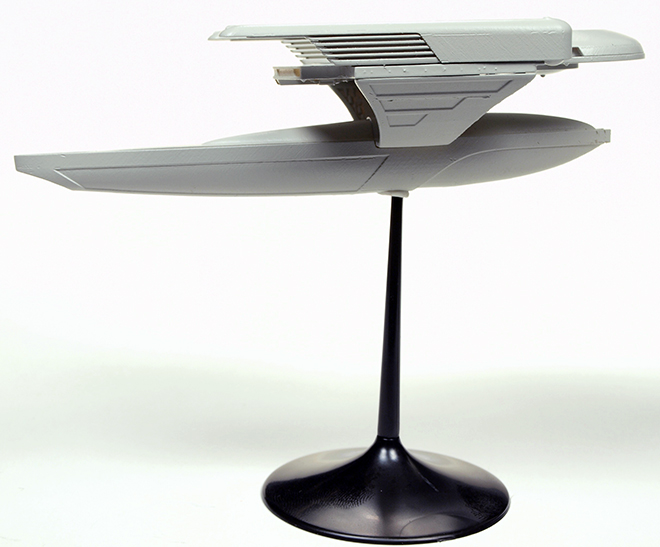
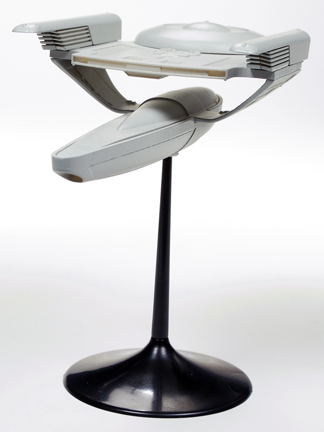
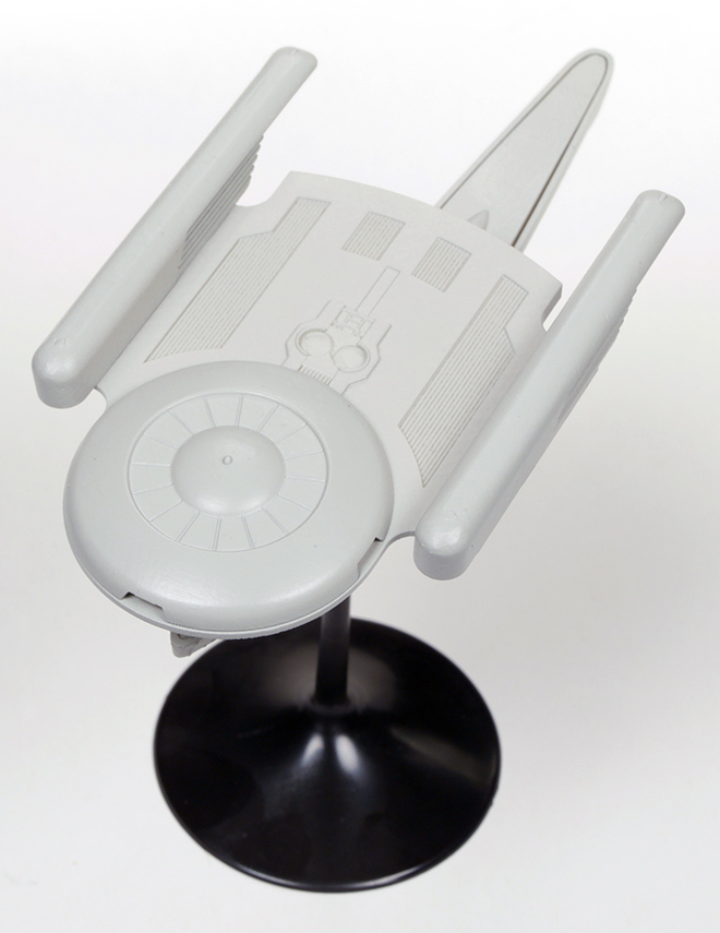
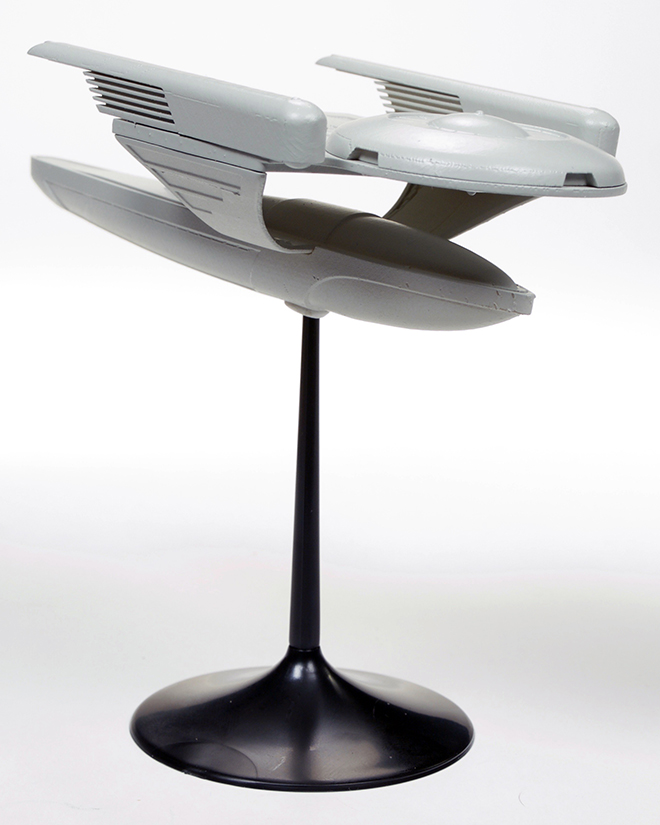
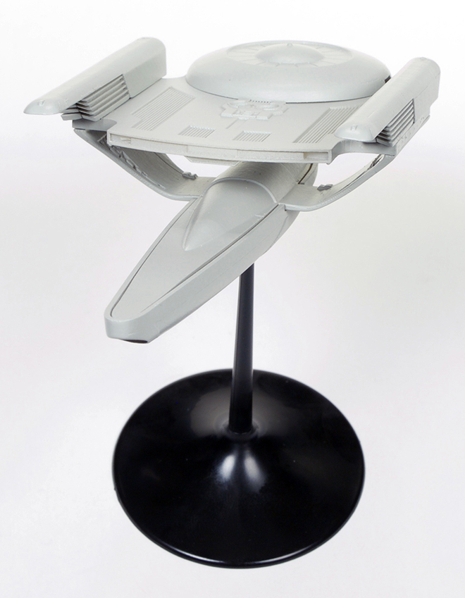
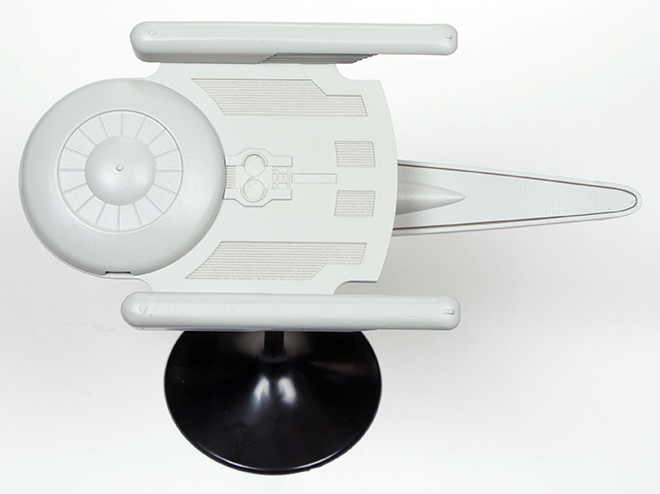
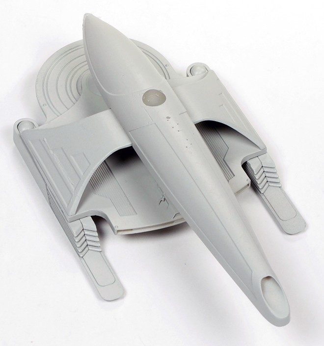
Star Trek Model Kits: U.S.S. Grissom & Klingon Bird-of-Prey 1:1000 scale
With a great license like STAR TREK, there is no end to the subjects we can introduce as new kits, but sometimes the question does arrive of “What should we do next?”. That question is usually tied to the investment needed for tooling the kit. It isn’t easy to do large, grand scale kits very often, but there are plenty of ships to consider at smaller scales like our popular 1:1000 scale kits. Except for maybe the Klingon K’t’inga, we have represented most of the recognizable ships in one scale or another. However, it seems like nearly every time we’ve asked modelers what ideas they had in mind, we often found one ship asked for over and over… The U.S.S. Grissom. The Oberth-class ship is a bit of a departure from the usual Starfleet fare. Though a fan-favorite, the Grissom was infamously taken out by a Klingon Bird-of-Prey in STAR TREK: The Search For Spock before other Oberths went on to appear in three more films and several episodes of ST:TNG. The ship is a relatively small design with an accepted length of 120 meters. That gave us bit of pause to do as a 1:1000 scale kit. A kit of this size wouldn’t be substantial enough to stand on its own. Though a 1:350 scale kit of the ship seems very appealing, we felt the need to check the reaction to a smaller investment first and come back to a large scale later if that seems feasible. So, what could we do? We could have reboxed our Enterprise Refit and included it in that like we did with the Botany bay in our TOS Enterprise kit, but I wanted to hold out on that and see if teaming the Refit with a dry dock kit might be viable later on. With the Refit still available and our recent U.S.S. Excelsior release, it became apparent that the last of the ships from STIII: The Search For Spock was the Klingon Bird-of-Prey. A smaller ship with a debatable length of about 90 meters, we could afford to team the two ships together in a 2-piece set and allow modelers to build a collection of every ship from that film. The KBoP is a beloved design and is in my personal list of top 5 space ship designs.
The Grissom is based on CAD work by Angelo Bastianelli and the KBoP will be based on our larger AMT kit. The Bird-of-Prey will come with two sets of wing baffles to build in either cruising or attack modes. Both kits will feature snap assembly to fit right in line with our other 1:1000 snap kits.
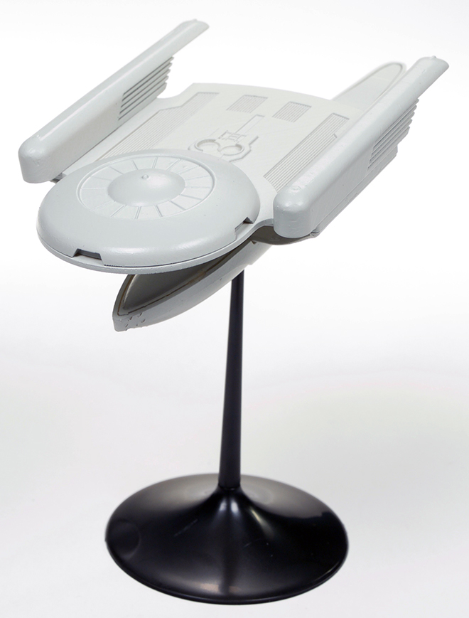
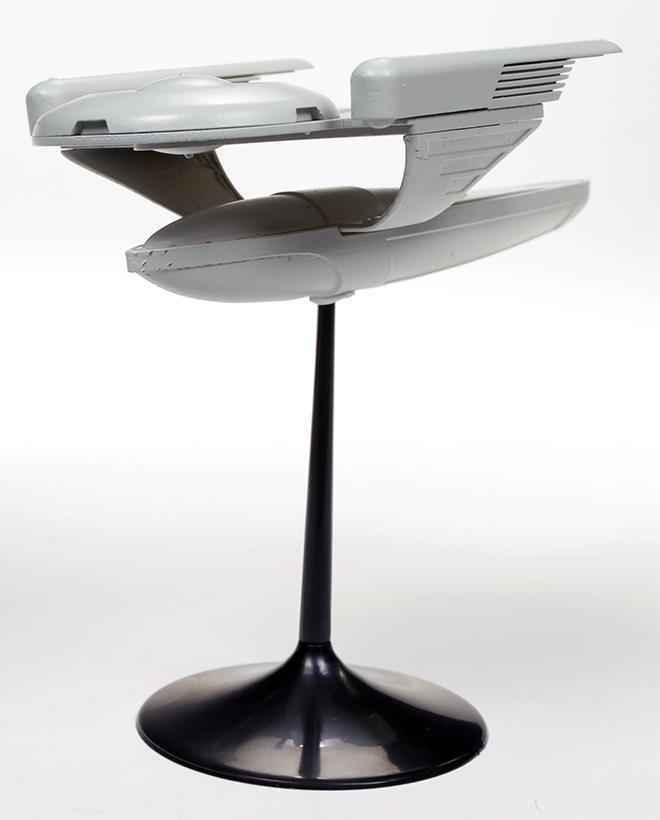
A few things to note on the mockups. On the Oberth, the factory made a couple mistakes. they grew an earlier copy of the deck. So the mockup shown here has the incorrect detail on the back the rear edge of the deck also shows more detail than we will end up with in production. They put a base rod hole in the bottom large enough to accept the rods for our 5″ dome bases, but these kits will come with our small bases, so that will be less obtrusive. On the KBoP, they forgot the base hole altogether. More significantly, they were supposed to grow two sizes of the ship. the one shown in thepics measures about 3 1/2″ long and would be comparable to the kit included in the AMT Adversary Set. At this length the ship would have been 90 meters long “in real life”. However, this deviates from the debated, but generally agreed to length of 110m. The second mockup was to be about 4 1/2″ long to bring it in scale with that measurement. The detail looks great at the smaller size, but we will most likely kick it up to the larger size. Let us know what you think in the comments.
Here, for the first time, is a look at the upcoming kits. The set is scheduled to be released by May 1st. So look for it at Wondefest 2018.
Now, I’ve been mulling “something” over… We are working on another brand-new kit. It will be big, and probably unexpected. I wish I could talk about it. It is really driving me nuts. It has been in the works for a long time already, and we are nearly finished with the CAD work. We will probably get a mockup within the month of January. I was hoping to hold out on this announcement until Wonderfest, but if we manage to stick to our development timeline, the kit should be out in August. In which case, we will probably announce it before that. I’ve been considering announcing it now as a Christmas gift to all of the sci-fi modelers out there. BUT, we all know how these things go. Any number of circumstances could crash down on the project. So I won’t say any more except…
Merry Christmas & Happy New Year! I hope one (or more) of your gifts is a model kit, but even more than that I hope you receive the peace and joy behind the season.