Recommended Sites


Posts Tagged ‘AMT’
Star Trek Models: My Enterprising Journey pt. 3
Here we are with Michael Scarola’s third part of his build process of our classic AMT U.S.S. Enterprise kit.
My Enterprising Journey: Building the Classic AMT 18” Enterprise – Part 3
There have been many discussions and articles that talk about the color of the TOS Enterprise studio model. On screen it appears anywhere from white to blue to green-gray to silver. It’s been revealed by Richard Datin that the studio model was actually a light gray with a hint of green. Datin chose the WalMart Concrete color chip as a near perfect match to the Enterprise’s hull color.
I started my research with a WalMart Concrete color chip and found Tamiya JN Grey appears to be a little too green. I had access to Gary Kerr’s actual paint samples of the hull color and the color that appears on the leading edge of the dorsal and also a sample that was matched to the Master Replicas TOS Enterprise.
The mixture I came up with is 3 parts Tamiya JN Grey, 1 part Sky Grey & 4 parts Flat White. It looks neutral with a color shift towards green when viewed under indoor lighting and it even appears to shift a bit blue at times. It’s right in the ballpark of the 3 samples and is very close to Gary Kerr’s hull color, only lighter, which is a good thing for the smaller scale AMT kit.
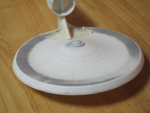
After the main hull color was painted I drew on the saucer grid with a pencil using the scaled blueprints, a straight piece of styrene sheet and a compass.
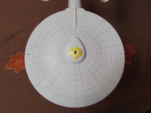
I mixed a darker shade of gray to pre-shade the grid lines and toned it down with the hull color.
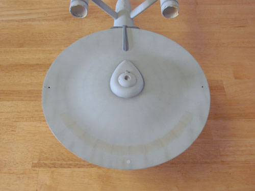
I mixed some Testors Acryl US Navy Blue Grey, Pale Green and Flat White for the leading edge of the dorsal and used Testors Acryl Neutral Gray for the darker colors. The nacelle grills are painted Tamiya Chrome Silver and the ends of the Intercoolers and Control Reactor are Testors Acryl Neutral Gray lightened with white. For the triangles on the bottom of the saucer and the darker areas on the undersides of the front of the nacelles I mixed a darker, more neutral, variant of the hull color.
Weathering and decals…
Dark gray and green pastels are used for most of the weathering and rust colored pastel chalk for the ‘rust ring’ on top of the saucer.
I did my best to represent most of the look of the weathering of the 11 foot studio model while toning it back a bit for this smaller project.
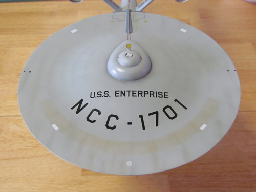
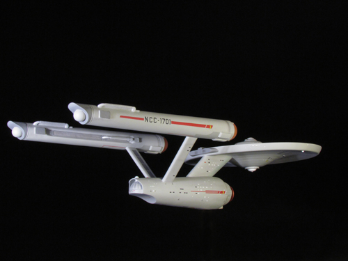
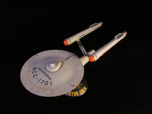
The decals that come with the Round 2 kit are very accurate. I did, however, separate the saucer’s U.S.S. ENTERPRISE/NCC-1701 decal into pieces. The ‘U.S.S. ENTERPRISE’ seemed to sit a bit too close to the ‘NCC-1701 and the spacing of the ‘U.S.S. was a bit too much compared with the 11 foot studio model. In addition I also separated the NCC-1701 into individual decals. This eliminated the clear film and due to the grid on the saucer I was able to place them according to the studio model’s placement. Other than this, the decals actually are very accurate. The below image shows the placement of the decals on the top of the saucer.
I sprayed Future floor polish over the model before applying the decals and sealed them with Testors Create FX acrylic flat clear, with a few drops of semi- gloss clear added to keep the surface from appearing chalky.
All in all I had a lot of fun working on this project. This is my first time building the AMT 18” TOS Enterprise and I’m glad I started with the Round 2 release. The smooth top of the saucer and the wonderful decal sheet really improved this classic kit.
I’d like to thank Jamie Hood and everyone at Round 2 for giving me the opportunity to share my build.
Michael Scarola
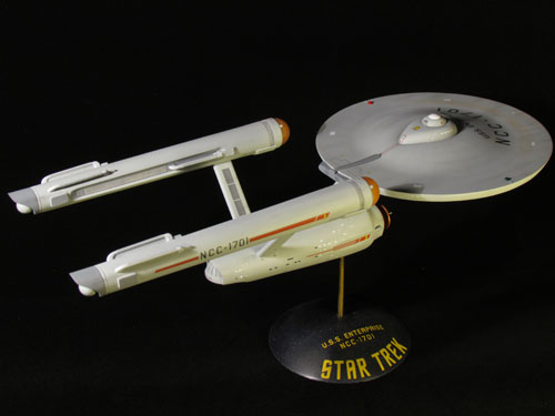
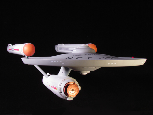
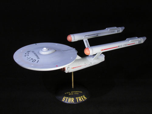
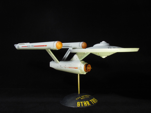
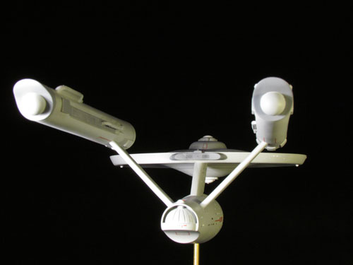
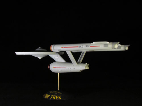
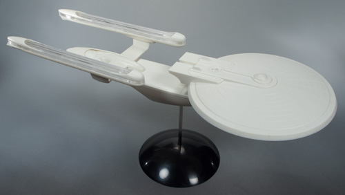
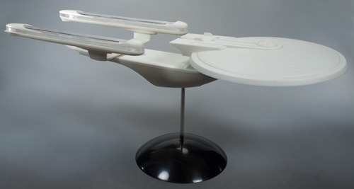
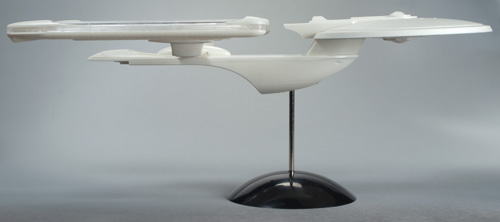
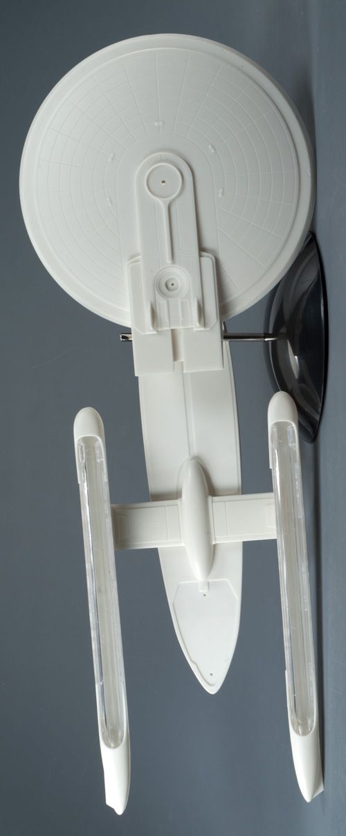
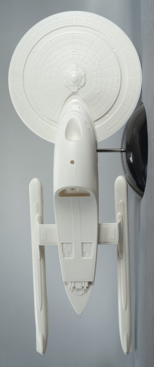
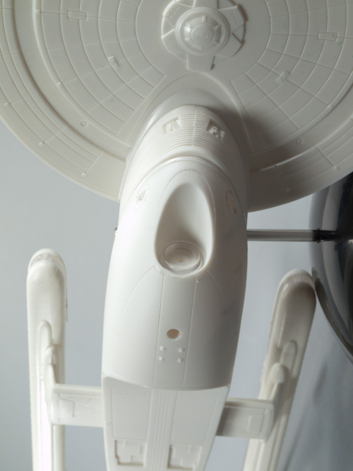
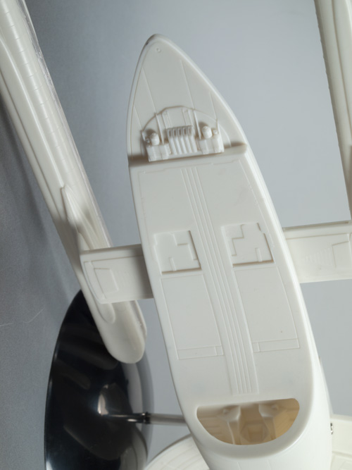
Take a bow, Mike. Great job. Have a gander at these beauty shots of the finished model.
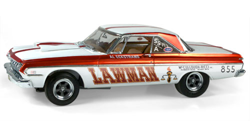
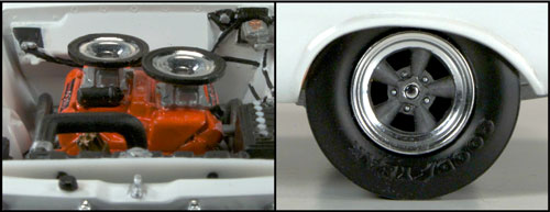
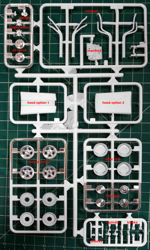
AMT Model kits: 1964 Belvedere Lawman NEW PARTS!
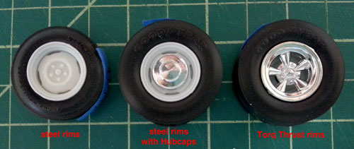
The long-rumored and anxiously awaited 1964 Belvedere 426 Super Stock Lawman will soon be here! With the release comes a few parts from new tooling. The shining features of the new tooling are the 2 all new sets of rims: a stock steel rim with an optional chrome hubcap and a Torq Thrust rim. New front spindles, rear blocks, and shocks will be included that enable the suspension to be raised or lowered, to achieve the proper wheel stance of the drag racer. The new parts will also include: racing headers, dual chrome air horns, intake manifold, chrome tachometer with oil gauge, and 2 different hood scoop options.
Accompany the new parts, the Lawman will have highly accurate decal sheet, updated instructions, chrome parts and vinyl drag slicks. The packaging will feature a full color tray and a new painting from Brad Leisure.
Star Trek models: My Enterprising Journey Pt. 2
Here we are with Michael Scarola’s second part of his build process of our classic AMT U.S.S. Enterprise kit.
My Enterprising Journey: Building the Classis AMT 18” Enterprise – Part 2
The work continues…
Now that the saucer’s details and shape were worked out it was time to move onto the secondary hull. I started by lengthening the hull. The 3 main parts were glued together and the rear section, in front of the pylons, was cut off and the hull was stretched approximately 1/16”.
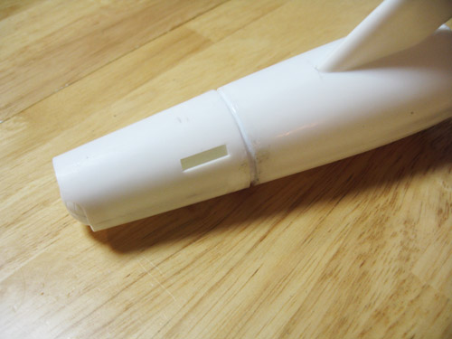
I used one of the AMT kit’s nacelle domes to make new landing bay doors by simply cutting it in half and scribing in some vertical lines.
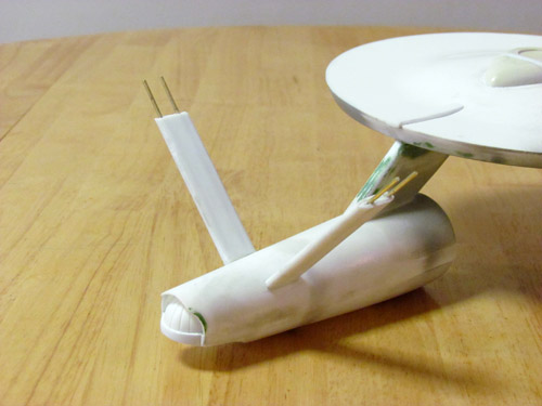
Sheet styrene was added to the curve of the hull next to the hanger bar doors to achieve the proper shape. The front of the hull was built up with putty and the ribbed details on the deflector forks were added using pieces of .5 mm styrene rod placed side by side as well as some half round styrene rods above and below.
I combined the rear of the kit’s deflector housing with the front of a resin housing from JT-Graphics. The outer housing itself was puttied and re-shaped.
The nacelle pylons were narrowed and shortened to match the blueprints. They were attached at an angle slightly less then 90 degrees using a template I made from the blueprints. I strengthened the pylons with sheet styrene and 1/8” brass rods.
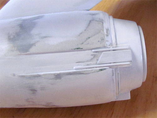
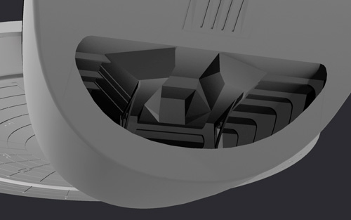
The kit’s nacelles were used and also modified. I cut off the grooves behind the bussard domes since I was using resin bussard domes from JT Graphics, which already these details. To create the taper of the studio model’s nacelles I drew a line with a pencil from the front corner of each half that goes to 2.5 mm at the rear.
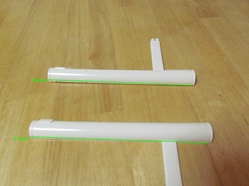
The above image illustrates where the cuts were made. Unfortunately I didn’t take a picture of the actual kit parts so I used nacelle halves from an older kit for figure 12’s illustration. It’s basically long skinny triangles that needed to be cut away. In order to make sure the inner trenches stayed centered on each nacelle the cut on both parts has to be made on the same side, as indicated in the picture. The 2 halves were heated with a hair dryer and rolled on a flat surface to create the taper towards the rear. When I glued the halves together I sanded, for what felt like days, to get them round and even.
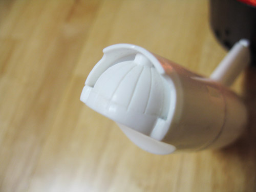
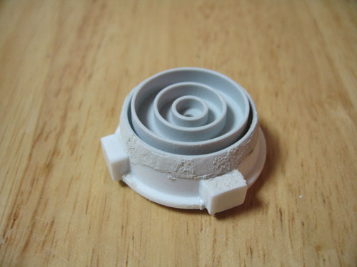
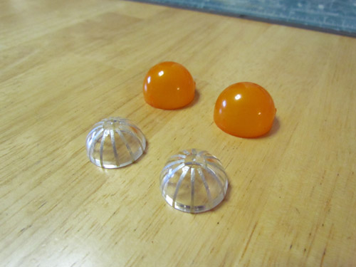
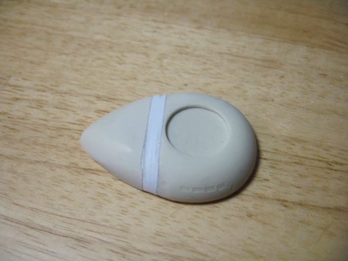
I used a set of correctly sized end caps from Federation Models that come with their Surya resin kit. The bussard domes from JT-Graphics have inserts to simulate the fan blades but have other details that weren’t actually on the studio model. Instead I used a set of clear domes I had on hand and added the fan blades with some 1 mm masking tape, painted silver.
I used a set of JT-Graphics Intercoolers and Federation Models Control Reactors and rear vents to round out the nacelle’s details.
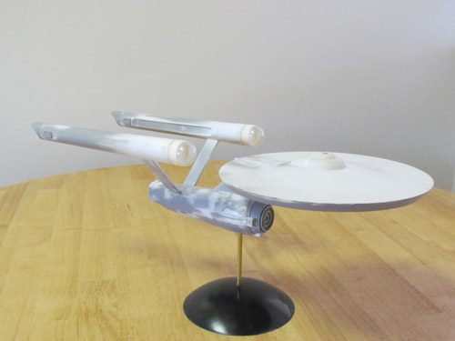
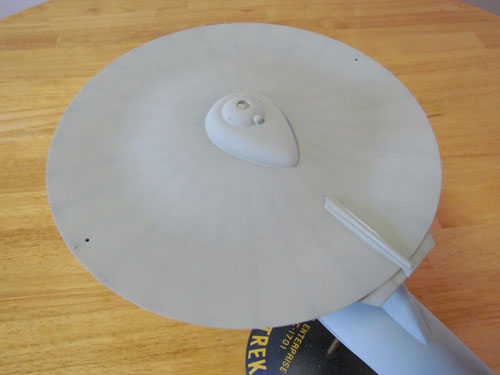
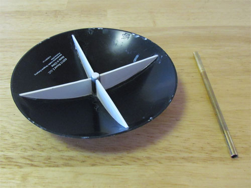
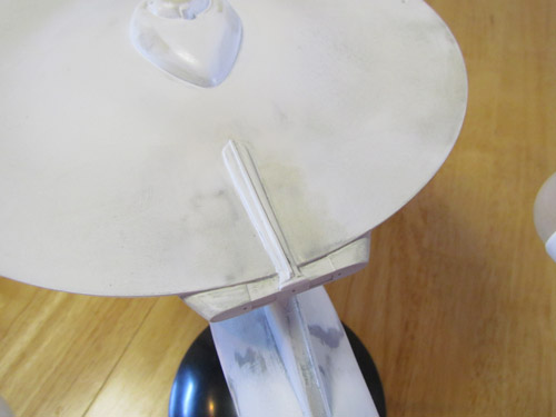
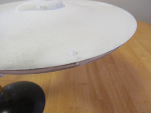
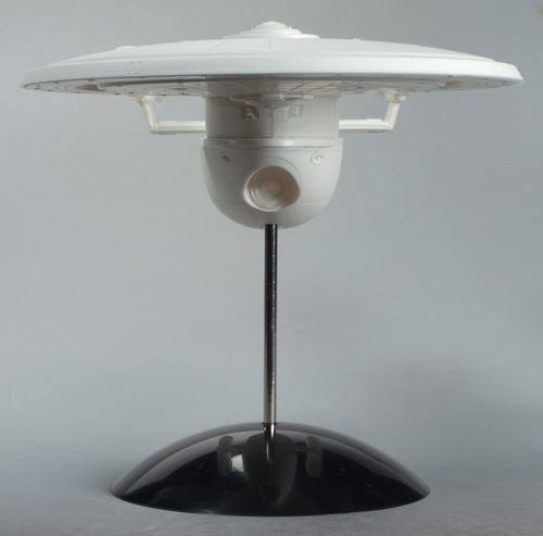
The above image shows the model almost completed sitting atop a Round 2 Dome Base, attached with a brass rod. I reinforced the dome base with 1 mm styrene sheet on the bottom. This keeps the Enterprise from swaying.
Having worked through all these modifications I was now ready to take a breath. The next round of fun would involve the hull color. With the Enterprise’s hull color being a big topic of debate over the years I knew it would take more then simply opening up a bottle of paint.
In my next and final installment I’ll cover the painting, weathering and the decals…
Michael Scarola
Round 2 Models: Please welcome a special guest
Hi guys. A while… a long while now… ago I was approached by a new, but respected modeler by the name of Michael Scarola. He was working on modifying a couple of our sci-fi kits and was pulling out all of the stops to make his buildups as accurate as the kits were iconic. We chatted a bit and we decided to have him document his process on the builds and post the results on our blog. We have had these in the can for some time now, but I’ve just come across a sliver of time to schedule them to publish.
Mike did some magnificent work to transform our classic 18″ AMT Star Trek U.S.S. Enterprise and our 12″ MPC Space:1999 Eagle. We’ll be starting with posts about his Enterprise model to coincide with our recent re-issue of the kit that commemorates the 50th anniversary of the television show. You should find the kit available now along with our re-issue of the Klingon Bird-of-Prey. Each series of articles will be three parts with some follow-ups showing beauty shots of his finished models. Off we go with part 1 of “My Enterprising Journey”. Enjoy!
My Enterprising Journey: Building the Classis AMT 18” Enterprise – Part 1
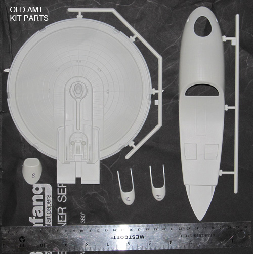
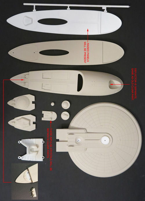
Round 2 has been doing a wonderful job bringing back classic models that we love. The classic AMT 18” TOS Enterprise has been released several times over the past few decades but Round 2’s release breathed new life into it. To start, the original box art was a real treat and the best part is under the lid. The raised grid from the earlier releases was removed from the saucer’s top and a new, and very accurate, set of decals is provided.
Onto the build!
My original intent was to build this kit mostly out of box with the addition of a few resin parts. I started by downloaded a set of blueprints from Charles Casimiro which I sized to the AMT saucer’s diameter. I figured once the saucer matched the blueprints all the rest would start falling into place. The profile of the dorsal (neck) matched the blueprints and I found that the secondary hull and warp nacelles also sized up nicely. At this point I decided to attempt to go all out and try and make this build resemble the 11 foot long Enterprise studio model that was seen in original Star Trek throughout the whole series.
I started by removing the bridge and B/C deck structure from the top of the saucer. I replaced it with a part from Don’s Light & Magic (DLM), which I lengthened by 4 mm.
I re-shaped the Linear Accelerator using a razor saw and various files.
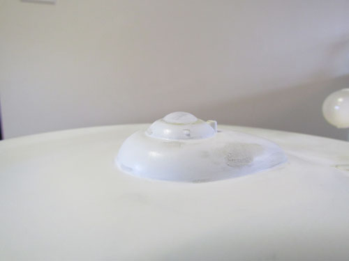
A new bridge dome was made using a spare nacelle dome from a Polar Lights 1/1000 TOS Enterprise kit.
The bottom of the saucer proved to be a bit of a challenge. I glued strips of 1 mm styrene inside the saucer’s edge so I would have enough plastic to re-shape the outer edge’s contour.
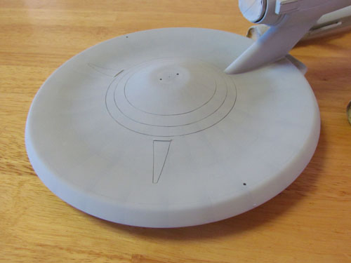
This was done using a razor saw, sanding sticks and lots of sanding. The 3 raised circular lines on the cone were removed and filled in as well as the 3 dimples by melting bits of plastic with liquid cement. The stepped area along the outer edge was removed and I added styrene sheet on the inside center of the cone and sanded down the raised area where the planetary censor attaches. The rest of the work involved sanding the bottom until it was even which seemed to go on forever. To scribe the 3 rings into the cone I used a compass cutter.
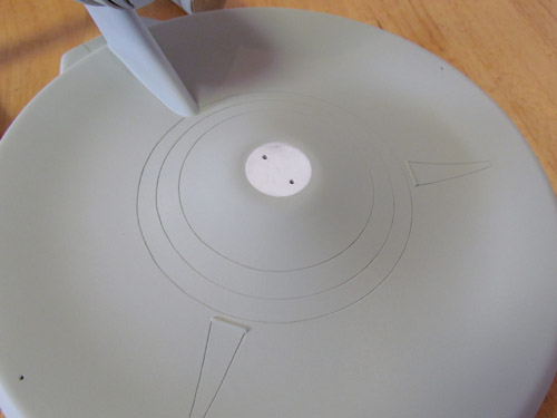
The above pic shows the completed work on the bottom of the saucer with the ‘triangles’ scribed in. For the navigation lights I used pieces of clear sprue from a Polar Lights 1/1000 TOS Enterprise kit. They are made to go in like pegs when the model is finished
The kit’s saucer does make an excellent platform to add details and modifications. The overall shape of the saucer is somewhat close to the studio model and just takes a bit of elbow grease to start looking the part. From the time I started my research this seemed like the most logical part to start on for the build.
In my next installment I’ll cover the secondary hull, nacelles, nacelle pylons, bussard domes and the base…
Michael Scarola
Star Trek Model Kits: U.S.S. Excelsior update
This time I’m coming back around to the Star Trek U.S.S. Excelsior model kit that should be coming by summertime. I received the first test shots a couple weeks ago and they look pretty good for the most part. There are always bugs to work out of course. The main thing about this particular set is the rough surface texture left from the RP that was used to make the electrodes that cut the tooling. Most of that work will be done by hand at the factory. The staff over there will need to take special care not to impact the nice delicate engraved panel lines we have on parts of the lower hull.
We made quite a few improvements on this version compared to the old AMT kit you might remember. In the end over half the kit was retooled including the entire lower hull. We used Gary Kerr’s notes and research on the aft weapon array and interior detail to get extremely close to the look of the filming miniature.
The parts are subject to licensor review.

Star Trek Models: U.S.S. Excelsior new part preview
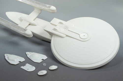
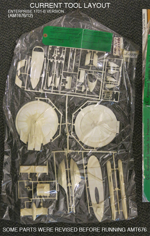
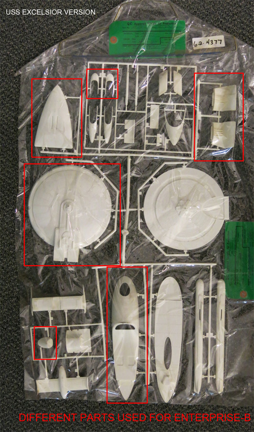
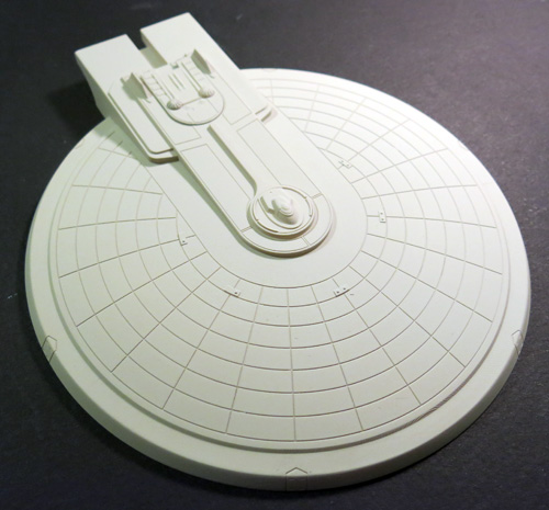
At long last, here is the promised sneak peek at the new parts that have been brewing to create our upcoming release of the U.S.S. Excelsior from Star Trek. The short history on the old AMT tooling is that the inserts that are needed to transform the U.S.S. Enterprise-B kit into the Excelsior have been lost. So we have had to recreate the missing parts. Like most of our work on new Star trek kits, the CAD work was done by Angelo Bastianelli. If you never picked up our reissue of the Enterprise-B a few years back, we made a few corrections on that one. Most significantly, we completely redid the lower saucer and curved the back wall of the neck. Some might ask if we are just recreating the parts from the old Excelsior kit. You know us by now. We approach these kits like the Six Million Dollar Man. We make them better than they were before, better stronger, faster… Okay, maybe just better, but you get the point.
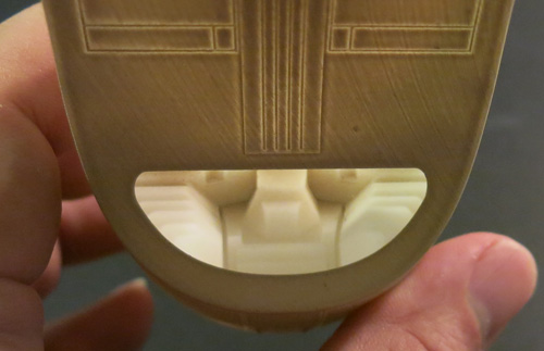
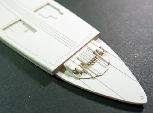
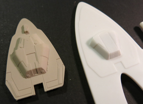
With this edition, we examined the shape of the lower hull carefully, but found that the shape of the old part was proportionally accurate. Without necessarily meaning to, the new one is relatively close to the shape of the old one. We’ve decided to implement a slide mold this time though so the deflector trench will no longer be a separate part. That also allows us to get the weapon details a little better on the sides of the hull. We are completely redoing the inner “gut” detail of the hull based on Gary Kerr’s research into the model kit parts used when the filming miniature was built. A few compromises were made to allow us to inject the part with minimal fuss, but few will pick up on the differences. The look of the “whalebone” is more accurate now with that detail being split between the inner bay part and the outer hull part.
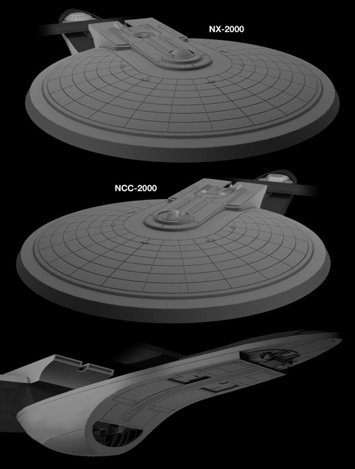
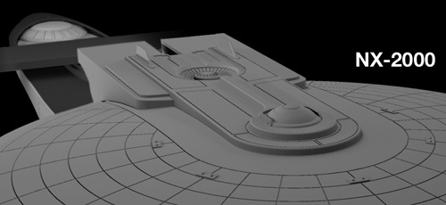
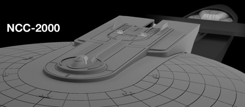
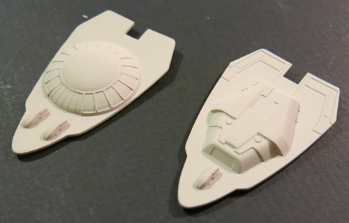
We had to recreate the top of the saucer as well and this was probably the most significant undertaking. The old part was kind of soft on details, so we made sure this one is up to snuff and a substantial upgrade will be the ability to use parts to build the ship as either the NX-2000 as shown in STAR TREK III: The Search For Spock or as the NCC-2000 as commanded by Sulu in STAR TREK VI: The Undiscovered Country. That means the bridge dome, impulse crystals and hangar bay will all come with swap-able parts. Speaking of impulse crystals, they will come as clear parts regardless of which version you choose.
Here are a whack of photos to take a gander at. I’m sure you’ll pick up on some of the other fun details and features I haven’t mentioned. Right now, it looks like the kit will be out in May.
For those hungry for more Eagle updates. I hope to have another post about that out next week.

Round 2 models: 1989 Batmobile
Hi guys. I know it has been a while since I have posted. My only excuse is my usual one of just not being able to find the time. Still, I feel guilty for not finding at least something quick to show you. So, I’m going to try to at least do a quick post every couple of weeks. It will be a sign of life at least. Wonderfest is coming up and I didn’t want to miss making the point that we’ll be there once again to meet face to face to talk about any of the sci-fi products we offer.
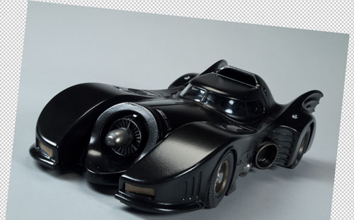
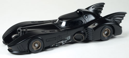
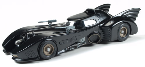
I recently got in a time pinch (can you believe it?). Our usual go-to car modeler, Mike Wherry, got buried in a small rush of buildup work and I was in need of a buildup of the AMT1989 Batmobile which will be coming out later this summer. I gave the kit a quick look and did a little poking around on the net to see what others had done with it. Eventually, I got to the point where I thought to myself, “Ya know. it isn’t a really complex kit. The car is all shades of black with some steel accents. Maybe I could build it myself and I could have it done in a couple weeks.” So I did.
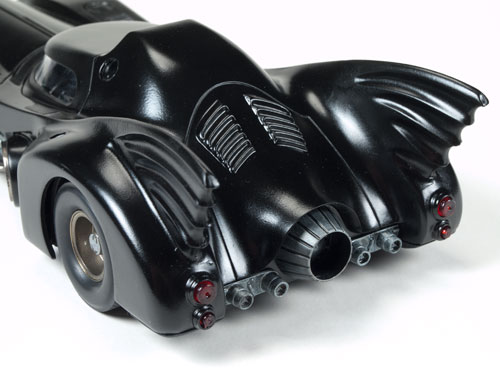
When I was a kid, I usually built cars and I left the hobby behind after getting frustrated with assembling engines that I never truly understood and with getting runs in the body paint. My younger brother on the other hand loved to chop tops and do mods to his cars. I couldn’t compete, so I built a couple jets and a couple of my dream cars before moving on to other things. The first Burton Batman film came out in the summer after my senior year in high school, and as a Batman fan I was a completist. So I bought and built an ’89 Batman kit when they first came out. So, as I was thinking about this build, I had vague memories of that one in mind. I remembered having to fill the seams in the tail fins and that there was a pull out turbine engine (only to relearn later that the pull-out feature was added to the Batman Returns edition which I would later buy). As you may know, I rarely build models to completion, but I fully understand the concepts and techniques used to build and finish them. The materials available these days and my ability to airbrush would give me a huge advantage over my younger attempt.
How did it go, you ask? Well enough for what I needed it for. I ran into the same problem I had as a youngster in that I got a little impatient with the spray paint (in this case a Testors lacquer). The first coat went down the best, but it didn’t cover 100% and my seams were still showing through. The second coat had runs and orange peel, so I sanded a bit and hit it again and a bit of orange peel remained, and some details started filling in, but it covered well enough and figured I could help the surface irregularity in Photoshop when I used it on the packaging. I’m sure that more practice with a rattle can would have gone a long way. If I had all the time in the world, and really wanted to do an outstanding job, I would have decanted the paint and ran it through my airbrush to get much better control.
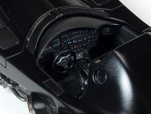
The interior turned out well enough though. I left the seat unpainted black plastic as I felt the sheen and color looked like vinyl or black leather. I hit some bits with flat black for contrast and try brushed the dials lightly enough to have them stand out, but not look heavy handed. I decided to hide most of the chrome to make it look more like the real thing. It was good enough to do the job, but I have nothing on the skills of someone like Mike Wherry.
It wasn’t until I was finished with my build that I realized that the last model I ever built and painted to completion was the same kit. Two builds nearly 25 years apart, and having done none (in styrene at least) in between. Anyway, I figured I would share the fruits of my labor. I’ll see if I can dig out my old build. I’m sure I’ve still got it in a box somewhere.
The first pic shows an unaltered pic of the buildup. The second shows how I plan to incorporate it into the box lid (pending licensor approval). The rest of the pics show a few other angles of the buildup.

The 4-H model – Finishing
Ensure that all paint and glue on your model is perfectly dry. It is good practice to start applying decals the day after you finish assembly and painting. Ensure also that your model is free of contaminants and dust, so nothing may be trapped underneath a decal.
Cut out all the decals you wish to apply with a sharp knife. It is not necessary to cut out the decals perfectly; rather you should leave a few millimeters around each decal to avoid cutting it accidentally.
Fill a bowl or shallow cup with warm water. The water should be at least lukewarm to remove the decals from the paper they are printed on, but not scalding hot. Never use boiling water to apply decals.
Hold the paper the decals are printed on with a pair of tweezers. Make sure you are not gripping a part of the decal itself under the tweezers.
We actually held the paper next to the car and gently slid the graphic onto the car. It is helpful if you get the car wet prior to sliding the graphic to help in positioning it. This will allow you a few seconds to slide the image into the place you want it.
Hold the paper the decal is printed on close to the part you are applying the decal to. The edge of the paper must be lying on the edge of the part, so the decal is transferred immediately from paper to part. Using a clean, wet brush, maneuver the decal onto the part and position it accordingly. Ensure that all air bubbles and creases are removed from the decal by pushing them out with the brush.
Dry the decal by very gently by dabbing it with a clean paper towel. The decal should be left alone for an hour to allow it to dry completely. Until then, it may be accidentally repositioned. To reposition a partially dry decal, simply apply some warm water with the brush and maneuver it back into position.
A few things we have learned…
- Remember that whatever paint-removing solvent you use, it must not harm plastic.
We do have a minor issue under the car where the solvent degraded the plastic a little,but it is underneath…
- Keep all empty sprues when you have finished assembly. They are useful for stirring paint, or making tools that won’t scratch the model you are working on.
These are also helpful for applying glue and you can throw them away when done.
- Keep all unused decals. You may later find them useful for other models.
- Some parts are more easily painted while left on the sprue.This is true particularly of very small parts for the engine. He chose to leave some the original color and chrome but that is an artistic choice.
- A torn decal is not useless. Careful positioning of the damaged portions can restore the decal to a whole appearance.This is where wetting the model can be handy and allow you to slide the decal into position.
- If your paint is too thick to feed through the airbrush, try diluting it with a small amount of rubbing alcohol. The alcohol thins the paint while it is in the airbrush, but evaporates soon after leaving it.
- When applying solvents, paints and glues, do so in a well-ventilated area. Observe all warnings and instructions printed on all your materials and tools.
- Knives and other sharp tools must be handled by experienced and responsible persons only.
- Small parts may pose a choking hazard to small children and animals.
The 4-H model…or starting it…
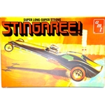
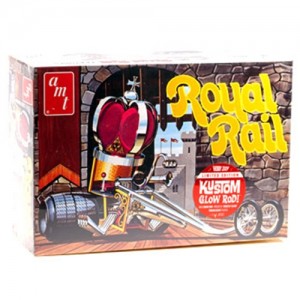
My son has selected the AMT Stingagree (http://www.autoworldstore.com/AMT_Stingaree_1_25_Scale_Model_Kit_p/amt38664.htm) which he will kitbash with pieces from the AMT Royal Rail (http://www.autoworldstore.com/AMT_Royal_Rail_ihobby_Exclusive_1_25_Scale_Model_K_p/amt630ihobby.htm). The Stingaree is described as a wild showrod-meets-dragster, which will be a perfect fit to kitbash with some of the wilder elements of the Royal Rail. But more on that later.
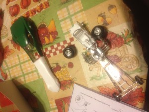
This year we are taking what we have learned over the last few years and combining the use of glue, paints, and decals to create a finished model – incorporating parts of another model.
In addition to the materials that are referenced above we have also purchased or at least gathered (and by we I mean I have purchased for my sweet 11 year old) the following items:
- Assorted paints (mostly greens – because he likes green)
- Plastic cement – several kinds including one especially for windows
- Tweezers and small nailclippers (these are great for trimming sharp bits from the sprue)
- Assorted elastic bands
- Modeling knife (this is my exacto knife – and used with my supervision)
- Small shears
- Masking tape – we do very little masking because the painting we do is pretty basic
- Paper towel
Some people would also include modeling putty and sand paper but we are also a little more basic. Now the rules say he could do any vehicle, spaceship, airplane, etc… but since this was the first year he has done a combination kit like this, I suggested something a little more basic. Our first few attempts were basic designs, snap together kits, then last year marked a new project where he had to both paint and glue.
The paint did not stick to the model, bubbled – badly. So when I started at Round 2 I set out to figure out just what had happened to avoid having it happen again.
1) So now that we have selected the model. This is not the kit he wanted, but we had to select one that was more advanced than some of his choices, and a little less exotic than others.
2) While we did not research these cars, we did visit the Auto World store to look for a model that we would like to do, that fit the requirements. We looked at the number of pieces, materials required to complete this project and the ability to modify this particular piece. Without the ability to see the step-by-step instructions – I think he made a good choice.
3) Next he had to look at the configuration. Configuration may include tires, accessories, the doors and windows open or closed, or even embellishments and exhaust pipes. In the case of the Stingaree, and the Royal Rail both offered many customization options.
GLUING A SNAP KIT IS A SNAP! …Part 3
Continued…
Puny Human Pin Hulk?
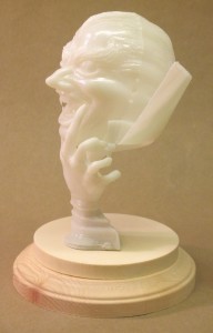
Whether you use the base that comes with the Hulk or you’re planning to use something different, I suggest you plan on pinning the big guy. Pinning isn’t difficult and will make your model more stable on its feet. It starts by filling the hollow foot assemblies with a solid material that will hold the mounting pins. I used epoxy putty that I pushed into the foot halves before I assembled them. The assembled feet could be filled with plaster of Paris just as well, but make sure all the water in the plaster has time to evaporate before you close up your model.
It hadn’t occurred to me to include pinning in this article when I was building my Hulk, so I will illustrate the procedure for pinning with another MPC snap-fit kit, the Vampire Glo-Head, Fig. 5. Round 2 has taken pains to make the model more stable than it was when originally issued, but I wanted to make sure it wouldn’t fall over at model contests. After the hand halves were joined, I filled the hollow interior with epoxy putty and sanded the bottom smooth.
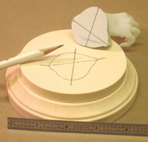
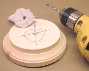
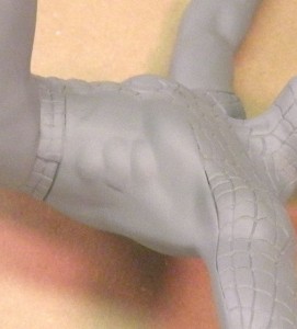
Then I needed to locate the hole in the resin and wood bases on which I would mount the model. This hole also had to line up with the epoxy plug in the base of the hand so it would sit in the proper position on the resin base. While I held the hand in position, I penciled four alignment marks around it, extending the marks onto the resin base. Then I connected the marks with the aid of a straightedge, locating the centers of the holes, Fig. 6. They were drilled into the hand and base; for this model, I used a big screw for the pin, Fig. 7. A section of sprue or a dowel would work also. I used this technique to pin Spider-man to his base as well.
If you’re reading this article in the first place, I presume you probably weren’t going to leave your Hulk unpainted. His upper body and feet assemblies were designed to be trapped by the trouser halves. It’s easy to paint the trouser parts and Hulk assemblies separately and then join them together.
The fit of the Hulk’s upper body to the top of his trousers isn’t the greatest, and the seams along the trouser halves are prominent. However, they appear where seams on real trousers do, so they don’t have to be eliminated for a realistic appearance. The pieces of the test shot I assembled had to be glued and clamped carefully to prevent them from coming apart. The gap between the Hulk’s torso and his trousers can be filled fairly easily (I brushed several layers of white glue in there) and the paint on the trousers touched up.
A Model of a Different Color
Everything I’ve had to say about gluing the snap-fit Incredible Hulk applies to the Amazing Spider-man – and all other snap-fit models, for that matter. Spidey was designed so the red and blue parts of his costume could be snapped together unpainted. The design itself is ingenious, but it makes life harder for the modeler who wants to assemble the model with glue.
I tried and failed to remove the mounting tabs from the hands and feet assemblies, thinking I could paint them separately from the body and attach them after painting. It would have been much easier to simply assemble Spider-man entirely (which I eventually did) and then paint him. This required a lot of masking, but the results were well worth the effort.
The hardest part was to get the red and blue sections to fit smoothly. I sort of cherry picked the areas where one section would have prominence over the other. And the usual seams reared their ugly heads under a coat of primer, Fig.8. I had to be careful not to fill the incised web pattern when filling gaps. Where I did fill the webbing, I tried to resculpt it with hobby knives and even a fine routing bit in a rotary tool – that proved unnecessary as we’ll see.
Painting the web pattern may seem daunting, but I found a few ways to make it easier. Over a good base of white primer, I painted the red areas of Spidey’s costume with an airbrush, using Testors Model Master Guard Red. This is a very bright red and dries to a gloss finish. To paint the webbing, I mixed a bit of liquid detergent with some Hunt’s black ink in a small cup. The soap broke the surface tension of the water-based ink so it wouldn’t puddle on the gloss red paint. Using a fine, pointed sable brush made it fairly easy to apply the ink into the incised webbing.
I found it best to plan ahead when applying the ink so that I could avoid grabbing a wet spot while holding the model. I began painting the back of Spidey’s boots – these were areas where I could practice painting the webbing without my mistakes being too noticeable (rubbing alcohol cleaned stray ink marks off the gloss red paint). I tended to hold the figure around the waist, so the next areas I painted were the arms, then the head, and finally the torso.
The ink dried rapidly; to prevent my finger oils from marring it or the red paint, I wore rubber gloves while I worked. I saw that the intensely black ink looked the same in the molded webbing as it did on any parts of it I had inscribed. Even flat surfaces where the webbing got filled looked okay; on its own the ink reinstated the detail very well.
Time to Celebrate!
– Because I’m done with this article and a couple of fine models. I was very impressed with the final appearance of these snap-fit kits. Their engineering made me take some different approaches to those I’d have made with glue kits, but the results were otherwise the same. I hope you enjoy building your models as much as I did mine.